TM 11-6625-3071-14
a.
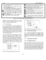
Loosen the screw on the rear of the 3478A’s top
cover and remove the cover.
b.
Locate the Line Select wire and the line
terminals. The wire and terminals are located near the
3478A’s power transformer (see Figure 2-2).
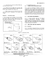
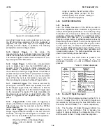
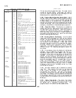
c. Refer to Figure 2-2 and connect the wire to the
line terminal which corresponds to the desired line
voltage.
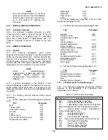
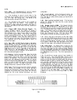
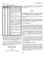
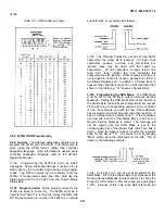
Figure 2.2. Line Select Jumper
d.
After changing the Line Voltage, mark the 3478A’s
rear panel to reflect the voltage change (mark the little
box under the instrument’s power cord receptacle that
corresponds to the new line voltage).
e.
Reinstall the top cover.
2-9. POWER CORDS AND RECEPTACLES
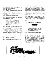
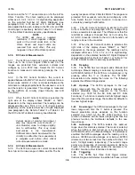
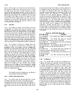
2-10. Figure 2-3 illustrates the different power plug
configurations that are available to provide power to the
3478A. The -hp- part number shown directly below the
individual power plug drawing, is the part number for the
power cord set equipped with the appropriate mating
plug for that receptacle. If the appropriate power cord is
not included with the instrument, notify the nearest -hp-
Sales/Service office and a replacement will be provided.
2-11. GROUNDING REOUIREMENTS
2-12. To protect operating personnel, the National
Electrical Manufacturing Association (NEMA)
recommendation is to ground the instrument panel and
cabinet. The 3478A is equipped with a three conductor
power cable which, when plugged into an appropriate
receptacle, grounds the instrument.
2-13. BENCH USE AND RACK MOUNTING
2-14. Bench Us
2-15. The 3478A is equipped with feet and tilt stands
installed and is ready for use as a bench instrument. The
Figure 2-2. Line Select Jumper
Figure 2-3. Power Cords
2-2
Содержание 3478A
Страница 2: ...TM 11 6625 3071 14 A ...
Страница 4: ...TM 11 6625 3071 14 C D BLANK ...
Страница 12: ...TM 11 6625 3071 14 Table 1 1 Specification 1 2 ...
Страница 13: ...TM 11 6625 3071 14 Table 1 1 Specifications Cont 1 3 ...
Страница 14: ...TM 11 6625 3071 14 Table 1 1 Specifications Cont 1 4 ...
Страница 53: ...TM 11 6625 3071 14 1 ...
Страница 54: ...TM 11 6625 3071 14 2 ...
Страница 55: ...TM 11 6625 3071 14 3 ...
Страница 56: ...TM 11 6625 3071 14 4 ...
Страница 87: ...TM 11 6625 3071 14 3478A Figure 7 D 3 Flowchart B 7 D 5 ...
Страница 88: ...TM 11 6625 3071 14 3478A Figure 7 D 4 Flowchart C 7 D 6 ...
Страница 91: ...TM 11 6625 3071 14 3478A Figure 7 D 6 Flowchart D 7 D 9 ...
Страница 98: ...TM 11 6625 3071 14 3478A Figure 7 F 2 Simplified Schematic Of The Input Switching Circuitry 7 F 4 ...
Страница 111: ...TM 11 6625 3071 14 Figure 7 F 17 3478A Simplified Reference Circuitry 7 F 16 ...
Страница 122: ...TM 11 6625 3071 14 Table A 2 A 2 HP IB Worksheet A 4 ...
Страница 137: ...TM 11 6625 3071 14 Figure 7 D 2 Flow chart A 7 D 3 ...
Страница 139: ...TM 11 6625 3071 14 Figure 7 G 2 3478A Block Diagram 7 G 3 ...
Страница 140: ...TM 11 6625 3071 14 Component Locator for Input Circuitry and Ohms Current Source 7 G 4 ...
Страница 141: ...TM 11 6625 3071 14 Figure 7 G 3 Input Circuitry and Ohms Current Source 7 G 5 ...
Страница 142: ...TM 11 6625 3071 14 F G 6 ...
Страница 143: ...TM 11 6625 3071 14 2 Figure 7 G 4 AC to DC Converter 7 G 7 ...
Страница 144: ...TM 11 6625 3071 14 Component Locator for A D Converter and Control Logic 7 G 8 ...
Страница 145: ...TM 11 6625 3071 14 3 Figure 7 G 5 A D Converter and Control Logic 7 G 9 ...
Страница 146: ...TM 11 6625 3071 14 7 G 10 ...
Страница 147: ...TM 11 6625 3071 14 4 Figure 7 G 6 Power Supplies 7 G 11 7 G 12 blank ...
Страница 148: ......
Страница 149: ...PIN NO 057444 ...


