


TM 11-6625-3071-14
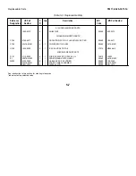
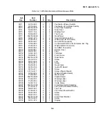
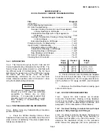
Table 5-2. Code List of Manufacturers
Mfr.
No.
Manufacturer Name
Address
0049D
United Chemicon Inc
01121
Allen-Bradley Co
Milwaukee WI 53204
01295
Texas Instr Inc Semicond Cmpnt Div
Dallas TX 75222
0192B
RCA Corp Solid State Div
Somerville NJ 08876
03888
KDI Pyrofilm Corp
Whippany NJ 07981
04713
Motorola Semiconductor Products
Phoenix AZ 85062
06665
Precision Monolithics Inc
Santa Clara CA 95050
07263
Fairchild Semiconductor Div
Mountain View CA 94042
07716
TRW Inc Burlington Div
Burlington IA 52601
11236
Cts of Berne Inc
Berne IN 46711
12969
Unitrode Corp
Watertown MA 02172
14936
General Instr Corp Semicon Prod Gp
Hicksville NY 11802
24355
Analog Devices Inc
Norwood MA 02062
24546
Corning Glass Works (Bradford)
Bradford PA 16701
27014
National Semiconductor Corp
Santa Clara CA 95051
28480
Hewlett-Packard Co Corporate Hq
Palo Alto CA 94304
56289
Sprague Electric Co
North Adams MA 01247
75915
Littlefuse Inc
Des Plaines IL 60016
designator column are available only for repair and
service of Hewlett-Packard Instruments.
5-12. 3478A DISASSEMBLY PROCEDURE
5-13. The following is the disassembly procedure for the
3478A.
a. Refer to Figure 5-2. Loosen the screw on the
3478A’s top cover (MP6). Turn the instrument over and
loosen the screw on the bottom cover (MP10).
b. Remove the bottom cover by pulling the cover
toward the rear of the 3478A and away from the
multimeter.
c. Turn the 3478A right side up. Remove the top
cover by pulling the cover toward the rear of the 3478A
and away from the multimeter.
d. See Figure 5-6. Remove the front and rear
panel wires from clamp MP26.
e. See Figure 5-4. Loosen and remove the screws
on both the left and right side side covers (MP4).
Remove the covers.
f. Refer to Figure 5-5. Loosen and remove screws
MP21 on the bottom plastic shield (MP23). Remove the
shield.
g. Refer to Figure 5-4. Loosen and remove screws
MP17 on the left side frame of the 3478A.
h. Refer to Figure 5-4. Loosen and remove screws
MP17 at the 3478A’s side frames (on both the left and
right side). Remove the side frames.
i. Unplug the HP-IB, Voltmeter Complete, External
Trigger, and Rear Panel Terminal Cables from the
mother board (A1 assembly).
j. Carefully remove the rear frame (MP18) and rear
panel (MP7) by pulling the frame toward the rear and
away from the instrument.
k. Refer to Figure 5-6. Using a small flat blade
screwdriver, insert the screwdriver blade into one slot of
the top trim (MP29) and remove the trim. Then loosen
and remove screws MP20 from the top side of the front
frame (MP13).
l. Refer to Figure 5-5. Loosen screws MP20 from
the bottom side of the front frame (MP13).
m. Remove the front frame (MP13) by pulling the
frame toward the rear and away from the instrument. Be
careful that the casting does not get tangled up in the
wires going to the front and rear terminals.
n. Refer to Figure 5-7. Loosen and remove screws
MP32 (also see Figure 5-8), from the bottom front panel
bracket (MP33) and remove the bracket.
o. Unplug the cable from the display.
p. Refer to Figure 5-7. Loosen and remove screws
MP34 from the front panel connector. Remove the front
panel assembly from the mother board (A1 assembly).
This completes the disassembly of the 3478A. If the
display is to be removed, continue with the next step.
q. To remove the display from the front panel,
loosen and remove screws MP32 (see Figure 5-8) from
the front panel assembly. Remove the display. This
completes the front panel disassembly.
5-2
Содержание 3478A
Страница 2: ...TM 11 6625 3071 14 A ...
Страница 4: ...TM 11 6625 3071 14 C D BLANK ...
Страница 12: ...TM 11 6625 3071 14 Table 1 1 Specification 1 2 ...
Страница 13: ...TM 11 6625 3071 14 Table 1 1 Specifications Cont 1 3 ...
Страница 14: ...TM 11 6625 3071 14 Table 1 1 Specifications Cont 1 4 ...
Страница 53: ...TM 11 6625 3071 14 1 ...
Страница 54: ...TM 11 6625 3071 14 2 ...
Страница 55: ...TM 11 6625 3071 14 3 ...
Страница 56: ...TM 11 6625 3071 14 4 ...
Страница 87: ...TM 11 6625 3071 14 3478A Figure 7 D 3 Flowchart B 7 D 5 ...
Страница 88: ...TM 11 6625 3071 14 3478A Figure 7 D 4 Flowchart C 7 D 6 ...
Страница 91: ...TM 11 6625 3071 14 3478A Figure 7 D 6 Flowchart D 7 D 9 ...
Страница 98: ...TM 11 6625 3071 14 3478A Figure 7 F 2 Simplified Schematic Of The Input Switching Circuitry 7 F 4 ...
Страница 111: ...TM 11 6625 3071 14 Figure 7 F 17 3478A Simplified Reference Circuitry 7 F 16 ...
Страница 122: ...TM 11 6625 3071 14 Table A 2 A 2 HP IB Worksheet A 4 ...
Страница 137: ...TM 11 6625 3071 14 Figure 7 D 2 Flow chart A 7 D 3 ...
Страница 139: ...TM 11 6625 3071 14 Figure 7 G 2 3478A Block Diagram 7 G 3 ...
Страница 140: ...TM 11 6625 3071 14 Component Locator for Input Circuitry and Ohms Current Source 7 G 4 ...
Страница 141: ...TM 11 6625 3071 14 Figure 7 G 3 Input Circuitry and Ohms Current Source 7 G 5 ...
Страница 142: ...TM 11 6625 3071 14 F G 6 ...
Страница 143: ...TM 11 6625 3071 14 2 Figure 7 G 4 AC to DC Converter 7 G 7 ...
Страница 144: ...TM 11 6625 3071 14 Component Locator for A D Converter and Control Logic 7 G 8 ...
Страница 145: ...TM 11 6625 3071 14 3 Figure 7 G 5 A D Converter and Control Logic 7 G 9 ...
Страница 146: ...TM 11 6625 3071 14 7 G 10 ...
Страница 147: ...TM 11 6625 3071 14 4 Figure 7 G 6 Power Supplies 7 G 11 7 G 12 blank ...
Страница 148: ......
Страница 149: ...PIN NO 057444 ...


