TM 11-6625-3071-14
3478A
3-116. Fast Trigger. This trigger mode can only be
selected over the HP-IB. It is the same as the Single
Trigger, except the delays in the AC Volts Function, AC
Current Function, and the high Ohms Ranges are
omitted. The mode can be selected by sending program
codes "TS".
3-117. Advanced Programming
3-118. General. The following paragraphs have
advanced programming information for the 3478A. It
includes Extended Ohms Operation, Reading the Binary
Status Byte, and Reading the Error Register. 3-119.
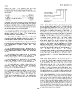
Extended Ohms Operation. This operation (or function)
is only available over the HP-IB and is used to measure
resistance above 30M ohm. The function is selected by
sending program code "F7" or "H7" (Home Command,
see paragraph 3-110). The 3478A is set to the 2-Wire
Ohms Function and the 30M ohm Range. A 10M ohm
resistor is connected in parallel with the input. Measure
the resistance first and then measure the unknown
resistance. The unknown resistance can then be
calculated by this formula:
Ri * Rt
Rx =
Ri - Rt
where Rx is the unknown resistance, Ri is the measured
10M ohm resistor, and Rt is the measured value of the
parallel combination.
3-120. Reading the Binary Status Byte. The current
status (or state) of the 3478A can be determined by
reading its Binary Status Byte. The total number of bytes
is five, with each byte 8 bits wide. The bytes can be read
by sending program code "B" to the 3478A and then
reading its output. A small program to read the output
using the -hp- Model 85 Personal Computer is as
follows:
10 OUTPUT 723 ;"B"
20 ENTER 723 USING "5(IB)" ;BI,B2,B3,B4,B5
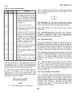
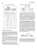
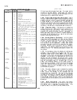
The bytes are in variables B1, B2, B3, B4, and B5. The
bytes and corresponding meanings of the bits (when
true) are in Table 3-7. Program Code "B" clears the
Error Register (byte 4; see Table 3-7).
3-121. Reading the Error Register. Besides using
Binary Status Byte 4 (see previous paragraph), the
status of the Error Register can also be determined by
sending program code "E" to the 3478A and then reading
its output. The output is a two digit octal number
followed by a carriage return and line feed. The number
shows which bit(s) of the register is true (a two digit
number can be used since only 6 bits are used by the
register). For example, bits 0 and 5 are true which results
in octal "41" (the maximum value is "77"). Refer to Table
3-7 (byte 4) for the definitions of the bits. The Error
Register is also cleared by sending program code "E".
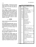
Table 3-7. Binary Status Byte Definition
Byte #
Definition
1
Bits
Function, Range, and Number Of Digits
True
Displayed
XXXXXX01
5 1/2 Digits Displayed
XXXXXX10
4 1/2 Digits Displayed
XXXXXX11
3 1/2 Digits Displayed
XXXO01XX
30mV DC, 300mV AC, 30 Ohm, 300mA AC or
DC, or Extended Ohms Ranges
XXX010XX
300mV DC, 3V AC, 300 Ohm, 3A AC or DC Ranges
XXX011XX
3V DC, 30V AC, 3K Ohm Ranges
XXX100XX
30V DC, 300V AC, 30K Ohm Ranges
XXX101XX
300V DC, 300K Ohm Ranges
XXX110XX
3M Ohm Range
XXX111XX
30M Ohm Range
001XXXXX
DC Volts Function
010XXXXX
AC Volts Function
011XXXXX
2-Wire Ohms Function
100XXXXX
4-Wire Ohms Function
101XXXXX
DC Current Function
110XXXXX
AC Current Function
111XXXXX
Extended Ohms Function
2
Bit#= 1
Instrument Status Bits
0
Internal Trigger Enabled
1
Autorange Enabled
2
Autozero Enabled
3
3478A set for 50Hz Operation
4
Front/Rear Switch in Front Position
5
Calibration RAM Enabled
6
External Trigger Enabled
7
Always Zero (not true)
3
Bit# = 1
SRQ Mask
0
Data Ready - SRQ for every available reading to the
HP-IB
1
Not used
2
Syntax Error - SRQ if Syntax Error occurs
3
Internal Error - SRO if Hardware Error occurs
4
Front Panel SRQ - SRQ If SRQ button is pressed
5
Calibration Error - SRO if CAL procedure failed
6
Always Zero (not true)
7
Power-On SRQ - PON SRQ switch on last time
power was turned on or DCL message was received
4
Bit# = 1
Internal Error Information
0
Set if any of the Calibration RAM locations have
incorrect checksums or if a range with an Incorrect
checksum is selected
1
The Main CPU RAM Self-Test has failed
2
The Control ROM Self-Test has failed
3
An A/D Slope Error was detected
4
The A/D has failed its Internal Self-Test
5
A failure in the A/D link (between U403 and U462)
6
Always Zero
7
Always Zero
5
Bits
A/D DAC Value
0-7
A decimal value between 0 to 63 represents the
setting of the internal Digital to Analog Converter
(DACI). (Refer to this manual’s Section VII for
Information.)
3-14
Содержание 3478A
Страница 2: ...TM 11 6625 3071 14 A ...
Страница 4: ...TM 11 6625 3071 14 C D BLANK ...
Страница 12: ...TM 11 6625 3071 14 Table 1 1 Specification 1 2 ...
Страница 13: ...TM 11 6625 3071 14 Table 1 1 Specifications Cont 1 3 ...
Страница 14: ...TM 11 6625 3071 14 Table 1 1 Specifications Cont 1 4 ...
Страница 53: ...TM 11 6625 3071 14 1 ...
Страница 54: ...TM 11 6625 3071 14 2 ...
Страница 55: ...TM 11 6625 3071 14 3 ...
Страница 56: ...TM 11 6625 3071 14 4 ...
Страница 87: ...TM 11 6625 3071 14 3478A Figure 7 D 3 Flowchart B 7 D 5 ...
Страница 88: ...TM 11 6625 3071 14 3478A Figure 7 D 4 Flowchart C 7 D 6 ...
Страница 91: ...TM 11 6625 3071 14 3478A Figure 7 D 6 Flowchart D 7 D 9 ...
Страница 98: ...TM 11 6625 3071 14 3478A Figure 7 F 2 Simplified Schematic Of The Input Switching Circuitry 7 F 4 ...
Страница 111: ...TM 11 6625 3071 14 Figure 7 F 17 3478A Simplified Reference Circuitry 7 F 16 ...
Страница 122: ...TM 11 6625 3071 14 Table A 2 A 2 HP IB Worksheet A 4 ...
Страница 137: ...TM 11 6625 3071 14 Figure 7 D 2 Flow chart A 7 D 3 ...
Страница 139: ...TM 11 6625 3071 14 Figure 7 G 2 3478A Block Diagram 7 G 3 ...
Страница 140: ...TM 11 6625 3071 14 Component Locator for Input Circuitry and Ohms Current Source 7 G 4 ...
Страница 141: ...TM 11 6625 3071 14 Figure 7 G 3 Input Circuitry and Ohms Current Source 7 G 5 ...
Страница 142: ...TM 11 6625 3071 14 F G 6 ...
Страница 143: ...TM 11 6625 3071 14 2 Figure 7 G 4 AC to DC Converter 7 G 7 ...
Страница 144: ...TM 11 6625 3071 14 Component Locator for A D Converter and Control Logic 7 G 8 ...
Страница 145: ...TM 11 6625 3071 14 3 Figure 7 G 5 A D Converter and Control Logic 7 G 9 ...
Страница 146: ...TM 11 6625 3071 14 7 G 10 ...
Страница 147: ...TM 11 6625 3071 14 4 Figure 7 G 6 Power Supplies 7 G 11 7 G 12 blank ...
Страница 148: ......
Страница 149: ...PIN NO 057444 ...


