TM 11-6625-3071-14
3478A
any readings in this step or step c are out of the specified
limits, go to the DC Volts Calibration Procedure in
paragraph 4-86.
e. (Step #7 and 8.) Remove the short from the
3478A’s INPUT Terminals and set the multimeter to the
30mV Range.
f. Set the DC Volts Standard for zero volts output. Set
the Digital Voltmeter to the DC Volts Function, 6 Digit
Display mode, and Autorange.
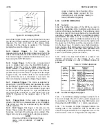
g. Connect the 3478A to the Digital Voltmeter and DC
Volts Standard, as shown in Figure 4-2. Use the Digital
Voltmeter as the standard and the DC Volts Standard as
the power supply. An example on how the Digital
Voltmeter and DC Volts Standard checks the 3478A
accuracy on the multimeter’s 3V Range, is as follows:
1. Set the 3478A to the 3V Range.
2. Set the DC Volts Standard for an output of +3V.
3. Note the reading on the Digital Voltmeter. If the
reading is not e3V, adjust the DC Volts Standard
until the reading is e 3V, as displayed by the
Digital Voltmeter. This reading is then the standard
voltage used to check the 3478A reading.
4. Make sure the 3478A reading is within its specified
limits. Record the reading on the Test Card.
NOTE
Always uprange the 3478A before
upranging the DC Volts Standard and
always downrange the DC Volts Standard
before downranging the 3478A.
Figure 4-2. DC Volts Accuracy Test and Calibration
h. Check the multimeter’s 30mV and 300mrnV
Ranges full scale accuracy by setting the DC Volts
Standard for an accurate output (as displayed on the
Digital Voltmeter) of 30mV and 300mV, respectively.
Check the multimeter’s readings and make sure they are
within the specified limits.
i. (Step #9.) Set the 3478A to the 3V Range and set
the DC Volts Standard for an accurate output of +
300mV. Check and record the reading.
j. (Step #10.) Set the DC Volts Standard for a + IV
output. Check and record the reading.
k. (Step #11.) Apply -IV to the 3478A by reversing the
input leads. (Leave the leads in that position for the next
step.) Check and record the reading.
l. (Step #12.) Set the DC Volts Standard for a 3V
output (-3V input to the 3478A). Check and record the
reading.
m. (Step #13.) Apply + 3V to the 3478A by reversing
the input leads. (Leave the leads in that position for the
steps that follow.) Check and record the reading.
n. (Step #14.) With + 3V applied to the 3478A, turn
Autozero off by pressing the blue Shift button and then
the INT/TRIG (AUTO/ZERO) button. Check and record
the reading.
o. (Step #15.) Turn Autozero on by pressing the blue
Shift button and then the INT/TRIG (AUTO/ZERO)
button.
p. (Step #16.) With + 3V applied to the 3478A, select
the multimeter’s 4 Digit Display mode by pressing the
blue Shift button and then the Uprange (4) button. Check
and record the reading.
q. (Step #17.) Select the 3478A’s 3 Digit Display mode
by pressing the blue Shift button and then the
AUTO/MAN (3) button. Check and record the reading.
r. (Step #18.) Select the 3478A’s 5 Digit Display mode
by pressing the blue Shift button and then the
Downrange (5) button.
s. (Step #19, 20, and 21.) Set the 3478A to the 30V
Range. Check the multimeter’s 1/10, 1/3, and full scale
accuracy by setting the DC Volts Standard for accurate
outputs of +3V, + 10V, and +30V, respectively. Check
and record the readings. Leave + 30V connected’ to the
3478A.
t. (Step #22.) With + 30V applied to the 3478A, turn
Autozero off by pressing the blue Shift button and then
the INT/TRIG (AUTO/ZERO) button. Check and’ record
the reading.
4-6
Содержание 3478A
Страница 2: ...TM 11 6625 3071 14 A ...
Страница 4: ...TM 11 6625 3071 14 C D BLANK ...
Страница 12: ...TM 11 6625 3071 14 Table 1 1 Specification 1 2 ...
Страница 13: ...TM 11 6625 3071 14 Table 1 1 Specifications Cont 1 3 ...
Страница 14: ...TM 11 6625 3071 14 Table 1 1 Specifications Cont 1 4 ...
Страница 53: ...TM 11 6625 3071 14 1 ...
Страница 54: ...TM 11 6625 3071 14 2 ...
Страница 55: ...TM 11 6625 3071 14 3 ...
Страница 56: ...TM 11 6625 3071 14 4 ...
Страница 87: ...TM 11 6625 3071 14 3478A Figure 7 D 3 Flowchart B 7 D 5 ...
Страница 88: ...TM 11 6625 3071 14 3478A Figure 7 D 4 Flowchart C 7 D 6 ...
Страница 91: ...TM 11 6625 3071 14 3478A Figure 7 D 6 Flowchart D 7 D 9 ...
Страница 98: ...TM 11 6625 3071 14 3478A Figure 7 F 2 Simplified Schematic Of The Input Switching Circuitry 7 F 4 ...
Страница 111: ...TM 11 6625 3071 14 Figure 7 F 17 3478A Simplified Reference Circuitry 7 F 16 ...
Страница 122: ...TM 11 6625 3071 14 Table A 2 A 2 HP IB Worksheet A 4 ...
Страница 137: ...TM 11 6625 3071 14 Figure 7 D 2 Flow chart A 7 D 3 ...
Страница 139: ...TM 11 6625 3071 14 Figure 7 G 2 3478A Block Diagram 7 G 3 ...
Страница 140: ...TM 11 6625 3071 14 Component Locator for Input Circuitry and Ohms Current Source 7 G 4 ...
Страница 141: ...TM 11 6625 3071 14 Figure 7 G 3 Input Circuitry and Ohms Current Source 7 G 5 ...
Страница 142: ...TM 11 6625 3071 14 F G 6 ...
Страница 143: ...TM 11 6625 3071 14 2 Figure 7 G 4 AC to DC Converter 7 G 7 ...
Страница 144: ...TM 11 6625 3071 14 Component Locator for A D Converter and Control Logic 7 G 8 ...
Страница 145: ...TM 11 6625 3071 14 3 Figure 7 G 5 A D Converter and Control Logic 7 G 9 ...
Страница 146: ...TM 11 6625 3071 14 7 G 10 ...
Страница 147: ...TM 11 6625 3071 14 4 Figure 7 G 6 Power Supplies 7 G 11 7 G 12 blank ...
Страница 148: ......
Страница 149: ...PIN NO 057444 ...

