


TM 11-6625-3071-14
SECTION VII
SERVICE
7-1. INTRODUCTION
7-2. This section of the manual has information on how
to troubleshoot and repair the 3478A multimeter with the
information given in Service Groups. Preliminary
troubleshooting procedures to select an appropriate
group are also given in Paragraph 7-27. It is
recommended to use the procedures first, before going
to a service group. Section VII also has the 3478A’s
complete Theory of Operation (in Service Group F), the
complete schematics (in Service Group G), and the
necessary safety considerations. The section is
separated as follows:
NOTE
The 3478A ’s Theory of Operation is in
Service Group F (next to the last group).
a. Safety Considerations - paragraph 7-3.
b. Recommended Test Equipment - paragraph 7-8.
c. Miscellaneous Information - paragraph 7-10.
1. Instrument Disassembly (PC Board
Replacement) - see Section V.
2. Fuse Replacement - paragraph 7-13.
d. Troubleshooting - paragraph 7-15.
1. Introduction - paragraph 7-16.
2. 3478A Self-Test - paragraph 7-18.
3. Service Group Selection - paragraph 7-27.
7-3. SAFETY CONSIDERATIONS
7-4. The 3478A has been designed with international
safety standards. To maintain these standards, the
cautions, warnings, and other safety related information
in this manual must be followed when servicing the
instrument. Servicing should only be done by qualified
service personnel.
7-5. Calibration, maintenance, or repair of the
instrument with covers removed while any power or
voltage is applied, should be avoided as much as
possible. If any work is done while power and/or voltage
is applied, the work should be carried out by a skilled
person who is aware of the hazards involved.
WARNING
Any interruptions of the protective grounding
conductor (inside or outside the instrument)
or disconnections of the protective earth
terminal can make the instrument
dangerous. Intentional interruption of the
protective grounding conductor is strictly
prohibited.
7-6. It is possible for capacitors inside the instrument to
remain charged when the instrument has been turned off
or its power source disconnected.
7-7. Make sure that only the recommended fuse type
(fast blow, correct current rating, etc.) is used for
replacement. The use of repaired fuses and the short-
circuiting of fuse holders must be avoided.
WARNING
The service information given in this manual
is normally used with the instrument’s
protective covers removed and with power
applied. Voltage or signals at many points
may, if contacted, result in personal injury.
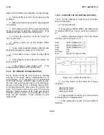
7-8. RECOMMENDED TEST EQUIPMENT
7-9. The recommended test equipment is listed in Table
4-2 in Section IV of this manual.
7-10. MISCELLANEOUS INFORMATION
7-11. Instrument Disassembly (PC Board Replace-
ment)
7-12. To replace the 3478A’s main printed circuit board,
the instrument must be completely disassembled. The
procedure to disassemble the instrument is in Section V
(Replaceable Parts) of this manual.
7-13. Fuse Replacement
7-14. The 3478A has two fuses, one fuse is the main
power fuse and the other one is to protect the instrument
in the DC and AC Current Functions. The fuses are
replaced as follows:
7-1
Содержание 3478A
Страница 2: ...TM 11 6625 3071 14 A ...
Страница 4: ...TM 11 6625 3071 14 C D BLANK ...
Страница 12: ...TM 11 6625 3071 14 Table 1 1 Specification 1 2 ...
Страница 13: ...TM 11 6625 3071 14 Table 1 1 Specifications Cont 1 3 ...
Страница 14: ...TM 11 6625 3071 14 Table 1 1 Specifications Cont 1 4 ...
Страница 53: ...TM 11 6625 3071 14 1 ...
Страница 54: ...TM 11 6625 3071 14 2 ...
Страница 55: ...TM 11 6625 3071 14 3 ...
Страница 56: ...TM 11 6625 3071 14 4 ...
Страница 87: ...TM 11 6625 3071 14 3478A Figure 7 D 3 Flowchart B 7 D 5 ...
Страница 88: ...TM 11 6625 3071 14 3478A Figure 7 D 4 Flowchart C 7 D 6 ...
Страница 91: ...TM 11 6625 3071 14 3478A Figure 7 D 6 Flowchart D 7 D 9 ...
Страница 98: ...TM 11 6625 3071 14 3478A Figure 7 F 2 Simplified Schematic Of The Input Switching Circuitry 7 F 4 ...
Страница 111: ...TM 11 6625 3071 14 Figure 7 F 17 3478A Simplified Reference Circuitry 7 F 16 ...
Страница 122: ...TM 11 6625 3071 14 Table A 2 A 2 HP IB Worksheet A 4 ...
Страница 137: ...TM 11 6625 3071 14 Figure 7 D 2 Flow chart A 7 D 3 ...
Страница 139: ...TM 11 6625 3071 14 Figure 7 G 2 3478A Block Diagram 7 G 3 ...
Страница 140: ...TM 11 6625 3071 14 Component Locator for Input Circuitry and Ohms Current Source 7 G 4 ...
Страница 141: ...TM 11 6625 3071 14 Figure 7 G 3 Input Circuitry and Ohms Current Source 7 G 5 ...
Страница 142: ...TM 11 6625 3071 14 F G 6 ...
Страница 143: ...TM 11 6625 3071 14 2 Figure 7 G 4 AC to DC Converter 7 G 7 ...
Страница 144: ...TM 11 6625 3071 14 Component Locator for A D Converter and Control Logic 7 G 8 ...
Страница 145: ...TM 11 6625 3071 14 3 Figure 7 G 5 A D Converter and Control Logic 7 G 9 ...
Страница 146: ...TM 11 6625 3071 14 7 G 10 ...
Страница 147: ...TM 11 6625 3071 14 4 Figure 7 G 6 Power Supplies 7 G 11 7 G 12 blank ...
Страница 148: ......
Страница 149: ...PIN NO 057444 ...


