TM 11-6625-3071-14
3478A
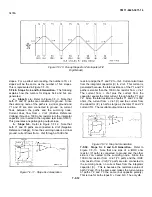
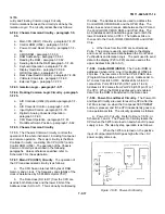
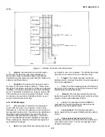
Figure 7-F-15. Determining the DAC Setting
S-4 current and the S-I current is 1/1000 the S-4 current.
The S + 2 and S + I currents use the same circuitry con-
figuration as the S+4 current (see Figure 7-F-11). In this
case, resistor values chosen are such that the S + 2
current is 1/100 the value of S+4 current and S+ 1 is
1/1000 the value of S+4.
7-F-49. A/D Converter and Reference Circuitry. The
A/D Converter Circuitry consists of the A/D Hybrid
(U403), A/D Integrator (U401 and associated circuitry),
A/D Controller (U462), and a DAC (U465 and associated
circuitry). Since the Voltage Reference Cir- cuitry (U461,
U405, U404, U402, and associated cir- cuitry) uses part
of the A/D Hybrid (for stability pur- poses) and since it is
also used by the A/D Converter, it is considered part of
the converter circuitry. Refer to Schematic 3 for the
following explanation on the A/D Converter Circuitry
(except for the DAC, see paragraph 7-F-46 and 7-F47
for its explanation).
a.
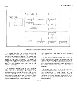
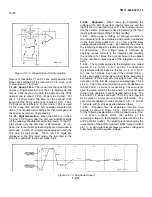
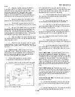
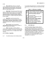
A/D Hybrid (U403). The A/D Hybrid, shown in
Figure 7-F-16, operates as follows:
1.The A/D Hybrid has, internal to it, various
latches, decoders, and a clock generator. The decoders
receive control information from the A/D Controller, then
decode the information and pass the new information to
the latches. The latches then transfer the new
information to the various switches in the hybrid during
each clock pulse. The clock pulses are generated by the
clock
Figure 7-F-16. A/D Hybrid (U403)
7-F-15
Содержание 3478A
Страница 2: ...TM 11 6625 3071 14 A ...
Страница 4: ...TM 11 6625 3071 14 C D BLANK ...
Страница 12: ...TM 11 6625 3071 14 Table 1 1 Specification 1 2 ...
Страница 13: ...TM 11 6625 3071 14 Table 1 1 Specifications Cont 1 3 ...
Страница 14: ...TM 11 6625 3071 14 Table 1 1 Specifications Cont 1 4 ...
Страница 53: ...TM 11 6625 3071 14 1 ...
Страница 54: ...TM 11 6625 3071 14 2 ...
Страница 55: ...TM 11 6625 3071 14 3 ...
Страница 56: ...TM 11 6625 3071 14 4 ...
Страница 87: ...TM 11 6625 3071 14 3478A Figure 7 D 3 Flowchart B 7 D 5 ...
Страница 88: ...TM 11 6625 3071 14 3478A Figure 7 D 4 Flowchart C 7 D 6 ...
Страница 91: ...TM 11 6625 3071 14 3478A Figure 7 D 6 Flowchart D 7 D 9 ...
Страница 98: ...TM 11 6625 3071 14 3478A Figure 7 F 2 Simplified Schematic Of The Input Switching Circuitry 7 F 4 ...
Страница 111: ...TM 11 6625 3071 14 Figure 7 F 17 3478A Simplified Reference Circuitry 7 F 16 ...
Страница 122: ...TM 11 6625 3071 14 Table A 2 A 2 HP IB Worksheet A 4 ...
Страница 137: ...TM 11 6625 3071 14 Figure 7 D 2 Flow chart A 7 D 3 ...
Страница 139: ...TM 11 6625 3071 14 Figure 7 G 2 3478A Block Diagram 7 G 3 ...
Страница 140: ...TM 11 6625 3071 14 Component Locator for Input Circuitry and Ohms Current Source 7 G 4 ...
Страница 141: ...TM 11 6625 3071 14 Figure 7 G 3 Input Circuitry and Ohms Current Source 7 G 5 ...
Страница 142: ...TM 11 6625 3071 14 F G 6 ...
Страница 143: ...TM 11 6625 3071 14 2 Figure 7 G 4 AC to DC Converter 7 G 7 ...
Страница 144: ...TM 11 6625 3071 14 Component Locator for A D Converter and Control Logic 7 G 8 ...
Страница 145: ...TM 11 6625 3071 14 3 Figure 7 G 5 A D Converter and Control Logic 7 G 9 ...
Страница 146: ...TM 11 6625 3071 14 7 G 10 ...
Страница 147: ...TM 11 6625 3071 14 4 Figure 7 G 6 Power Supplies 7 G 11 7 G 12 blank ...
Страница 148: ......
Страница 149: ...PIN NO 057444 ...

