


TM 11-6625-3071-14
b.
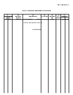
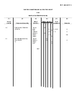
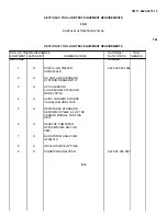
Column 2, Component/Assembly. Column 2 contains the noun names of components, assemblies,
subassemblies, and modules for which maintenance is authorized,
c.
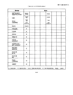
Column 3, Maintenance Functions. Column 3 lists the functions to be performed on the item listed column 2.
When items are listed without maintenance functions, it is solely for purpose of having the group numbers in the MAC and
RPSTL coincide.
d.
Column 4, Maintenance Category. Column 4 specifies, by the listing of a "work time" figure in the appropriate
subcolumn(s), the lowest level of maintenance authorized to perform the function listed in column 3. This figure
represents the active time required to perform that maintenance function at the indicated category of maintenance. If the
number or complexity of the tasks within the listed maintenance function vary at different maintenance categories,
appropriate "work time" figures will be shown for each category. The number of task-hours specified by the "work time"
figure represents the average time required to restore an item (assembly, subassembly, components, module, end item or
system) to a serviceable condition under typical field operating conditions. This time includes preparation time, trouble
shooting time, and quality assurance/quality control time in addition to the time required to perform the specific tasks
identified for the maintenance function authorized in the maintenance allocation chart. Subcolumns of column 4 are as
follows:
C - Operator/Crew
O - Organizational
F - Direct Support
H - General Support
D - Depot
e. Columns 5, Tools and Equipment. Column 5 specifies by code, those common tools sets (not individual tools) and
special tools, test, and support equipment required to perform the designated function.
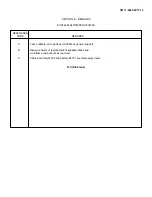
f. Column 6, Remarks. Column 6 contains as alphabetic code which leads to the remark in section IV, Remarks,
which is pertinent to the item opposite the particular code.
D-3
Содержание 3478A
Страница 2: ...TM 11 6625 3071 14 A ...
Страница 4: ...TM 11 6625 3071 14 C D BLANK ...
Страница 12: ...TM 11 6625 3071 14 Table 1 1 Specification 1 2 ...
Страница 13: ...TM 11 6625 3071 14 Table 1 1 Specifications Cont 1 3 ...
Страница 14: ...TM 11 6625 3071 14 Table 1 1 Specifications Cont 1 4 ...
Страница 53: ...TM 11 6625 3071 14 1 ...
Страница 54: ...TM 11 6625 3071 14 2 ...
Страница 55: ...TM 11 6625 3071 14 3 ...
Страница 56: ...TM 11 6625 3071 14 4 ...
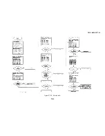
Страница 87: ...TM 11 6625 3071 14 3478A Figure 7 D 3 Flowchart B 7 D 5 ...
Страница 88: ...TM 11 6625 3071 14 3478A Figure 7 D 4 Flowchart C 7 D 6 ...
Страница 91: ...TM 11 6625 3071 14 3478A Figure 7 D 6 Flowchart D 7 D 9 ...
Страница 98: ...TM 11 6625 3071 14 3478A Figure 7 F 2 Simplified Schematic Of The Input Switching Circuitry 7 F 4 ...
Страница 111: ...TM 11 6625 3071 14 Figure 7 F 17 3478A Simplified Reference Circuitry 7 F 16 ...
Страница 122: ...TM 11 6625 3071 14 Table A 2 A 2 HP IB Worksheet A 4 ...
Страница 137: ...TM 11 6625 3071 14 Figure 7 D 2 Flow chart A 7 D 3 ...
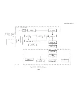
Страница 139: ...TM 11 6625 3071 14 Figure 7 G 2 3478A Block Diagram 7 G 3 ...
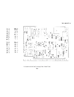
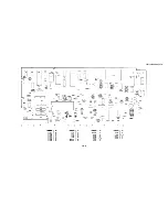
Страница 140: ...TM 11 6625 3071 14 Component Locator for Input Circuitry and Ohms Current Source 7 G 4 ...
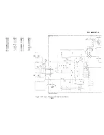
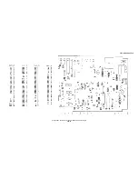
Страница 141: ...TM 11 6625 3071 14 Figure 7 G 3 Input Circuitry and Ohms Current Source 7 G 5 ...
Страница 142: ...TM 11 6625 3071 14 F G 6 ...
Страница 143: ...TM 11 6625 3071 14 2 Figure 7 G 4 AC to DC Converter 7 G 7 ...
Страница 144: ...TM 11 6625 3071 14 Component Locator for A D Converter and Control Logic 7 G 8 ...
Страница 145: ...TM 11 6625 3071 14 3 Figure 7 G 5 A D Converter and Control Logic 7 G 9 ...
Страница 146: ...TM 11 6625 3071 14 7 G 10 ...
Страница 147: ...TM 11 6625 3071 14 4 Figure 7 G 6 Power Supplies 7 G 11 7 G 12 blank ...
Страница 148: ......
Страница 149: ...PIN NO 057444 ...


