3478a
TM 11-6625-3071-14
7-C-8. Inaccurate Readings on All or Some Ranges
7-C-9. This failure is normally caused when the ohms
current changes value due to a load change. Do the
following procedure.
a. Set the 3478A to the 2-Wire Ohms Function and
the 3K ohm Range.
b. Connect a 3K ohm Resistor to the 3478A’s
INPUT Terminals.
c. Using a high impedance Digital Voltmeter (like
the 3456A), measure the voltage across R205. Since
the ohms current on the 3K ohm Range is 1mA, the
voltage should be approximately .47V dc.
d. If the voltage is radically wrong, the ohms current
is incorrect. Use the overload troubleshooting procedure
(in paragraph 7-C-6) to determine the faulty circuitry.
e. If the voltage is good, remove the 3K ohm
Resistor from the INPUT Terminals. Then short the
INPUT Terminals.
f. If the voltage across R205 changes, the Output
PMOS FET in U102 may be defective. Replace U102.
g. If the voltage remains the same, the failure is
most likely in the Ohms Protection Circuitry. Make sure
Q201 through Q204 are good.
7-C-10. Constant Zero Reading on All Ranges
7-C-11. A Constant Zero Reading is normally caused
when the Ohms Current Source supplies no ohms
current (current at zero value). Since no current goes
through the resistor to be measured, no voltage drop
across the resistor is developed and the 3478A
measures zero volts (zero reading). A no-current
condition can be caused by an open circuit between the
Ohms Current Source and the INPUT Terminals, or by a
defective Current Source. Do the following procedure.
a. Set the 3478A to the 2-Wire Ohms Function and
the 3K ohm Range.
b. Connect a 3K ohm Resistor to the 3478A’s
INPUT Terminals.
c. Using a clip lead, connect pin 15 of U102 to the
3478A’s HI INPUT Terminal.
d. If the 3478A still shows a constant zero reading,
the Ohms Current Source is inoperative. Go to
paragraph 7-C-20 for troubleshooting.
e. If the Ohms Function is now operating correctly,
do the following:
1. Disconnect the clip lead from pin 15 of U102
and connect it to the collector of Q204 (junction of
Q204, R203, and cathode of CR201). Leave the
other end of the clip lead connected to the input
terminal for the checks that follow.
2. If the Ohms Function is now operating, check
for an open R205 or an open in Q201 through
Q204.
3. If the Constant Zero Reading is still displayed,
disconnect the clip lead from Q204 and connect it to
the anode of CR201.
4. If the Ohms Function is now operating, check
for an open CR201.
5. If the Constant Zero Reading is still displayed,
check for an open K103. Make sure K103 is
energized (+5V across the relay coil), before
replacing the relay. If the relay is not energized,
U102 may be defective. Before replacing U102,
make sure the A/D Controller (U462) is good. Go to
paragraph 7-C-24 for the SA procedure to check
U462.
7-C-12. Noise on All Ranges
7-C-13. Noise on all ranges is normally caused by a
noisy ohms current. Do the following procedure.
a. Set the 3478A to the 2-Wire Ohms Function and
the 3K ohm Range.
b. Connect a 3K ohm Resistor to the 3478A’s
INPUT Terminals.
c. Using a clip lead, connect pin 15 of U102 to the
3478A’s HI INPUT Terminal.
d. If the Ohms Function is quiet, noise is caused by
the Ohms Protection Circuitry. Check Q201 through
Q204.
e. If the Ohms Function is still noisy, do the
following checks.
1. Using a high impedance Digital Voltmeter
(like the 3456A), make sure the voltage at U201 pin
6 is a quiet +8V (<10
µ
V change). Replace U201, if
noisy. If the voltage is still noisy, try U102.
2. If the voltage at U201 pin 6 is good, measure
for a quiet +12V at U202 pin 6 (<10
µ
V change).
Replace U202, if noisy. If the voltage is still noisy,
replace U102.
3. If the voltage at U202 pin 6 is good, replace
U203. If the ohms function is still noisy, replace
U102.
7-C-2
Содержание 3478A
Страница 2: ...TM 11 6625 3071 14 A ...
Страница 4: ...TM 11 6625 3071 14 C D BLANK ...
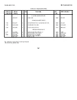
Страница 12: ...TM 11 6625 3071 14 Table 1 1 Specification 1 2 ...
Страница 13: ...TM 11 6625 3071 14 Table 1 1 Specifications Cont 1 3 ...
Страница 14: ...TM 11 6625 3071 14 Table 1 1 Specifications Cont 1 4 ...
Страница 53: ...TM 11 6625 3071 14 1 ...
Страница 54: ...TM 11 6625 3071 14 2 ...
Страница 55: ...TM 11 6625 3071 14 3 ...
Страница 56: ...TM 11 6625 3071 14 4 ...
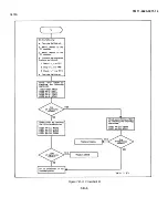
Страница 87: ...TM 11 6625 3071 14 3478A Figure 7 D 3 Flowchart B 7 D 5 ...
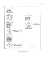
Страница 88: ...TM 11 6625 3071 14 3478A Figure 7 D 4 Flowchart C 7 D 6 ...
Страница 91: ...TM 11 6625 3071 14 3478A Figure 7 D 6 Flowchart D 7 D 9 ...
Страница 98: ...TM 11 6625 3071 14 3478A Figure 7 F 2 Simplified Schematic Of The Input Switching Circuitry 7 F 4 ...
Страница 111: ...TM 11 6625 3071 14 Figure 7 F 17 3478A Simplified Reference Circuitry 7 F 16 ...
Страница 122: ...TM 11 6625 3071 14 Table A 2 A 2 HP IB Worksheet A 4 ...
Страница 137: ...TM 11 6625 3071 14 Figure 7 D 2 Flow chart A 7 D 3 ...
Страница 139: ...TM 11 6625 3071 14 Figure 7 G 2 3478A Block Diagram 7 G 3 ...
Страница 140: ...TM 11 6625 3071 14 Component Locator for Input Circuitry and Ohms Current Source 7 G 4 ...
Страница 141: ...TM 11 6625 3071 14 Figure 7 G 3 Input Circuitry and Ohms Current Source 7 G 5 ...
Страница 142: ...TM 11 6625 3071 14 F G 6 ...
Страница 143: ...TM 11 6625 3071 14 2 Figure 7 G 4 AC to DC Converter 7 G 7 ...
Страница 144: ...TM 11 6625 3071 14 Component Locator for A D Converter and Control Logic 7 G 8 ...
Страница 145: ...TM 11 6625 3071 14 3 Figure 7 G 5 A D Converter and Control Logic 7 G 9 ...
Страница 146: ...TM 11 6625 3071 14 7 G 10 ...
Страница 147: ...TM 11 6625 3071 14 4 Figure 7 G 6 Power Supplies 7 G 11 7 G 12 blank ...
Страница 148: ......
Страница 149: ...PIN NO 057444 ...

