


TM 11-6625-3071-14
3478A
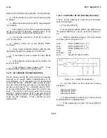
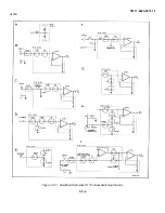
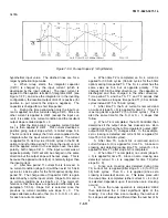
Figure 7-D-7. JM403 SA Connection
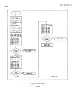
4.
If pin 3 of U466 is high, replace U466. If low,
replace U467.
c.
If the RESET line is high, while monitoring the
line, press the 3478A’s blue Shift button and then the
SGL/TRIB (TEST/RESET) button. The 3478A should go
through its Self-Test routine, and when the routine is
finished, the RESET line toggles from high to low to high.
d.
If the RESET line toggles and the 3478A is still
in- operative, replace U462.
e.
If the RESET line does not toggle, do the
following:
1.
Make sure pin 1 of U467 is toggling.
2.
If pin 1 is not toggling, the Isolation Cir- cuitry
may be at fault. Go to paragraph 7-D-44 for
troubleshooting.
3.
If pin 1 is toggling, replace U486 and then U467.
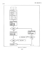
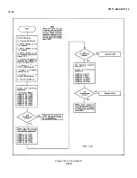
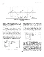
7-D-44. ISOLATION CIRCUITRY TROUBLESHOOTING
7-D-45. The Isolation Circuitry transfers information from
the Main Controller (U501) to the A/D Controller (U462)
and also from the A/D Controller to the Main Controller.
A failure in the logic is normally indicated when, after
doing a Self-Test, "A:D LINK FAIL" is displayed. To
troubleshoot the circuitry, first determine the inoperative
circuitry and then troubleshoot the cir- cuitry. Do the
following:
a.
Turn the 3478A off.
b.
Move jumpers JM502 and JM503 to the "D"
position.
c.
Connect the Floating Common ground to the
3478A’s chassis. The LO INPUT terminal can be
used as a Floating Common ground (make sure the cor-
rect terminal is used, dependent on the position of the
Front/Rear Switch).
d.
Connect and set the Signature Analyzer as
follows:
Start:
U462 pin 1 (
)
Stop:
TP8 (
)
Clock:
TP3 (
)
Hold:
Out
Self-Test: Out
Gnd:
Chassis Ground
e.
Turn the 3478A on and check the signature of
the Chassis 5V power supply.
f.
If the signature is different than "HF52" and the
SA probe is toggling, the Main Controller (U501) may be
defective. Go to Flowchart A for troubleshooting (see
paragraph 7-D-II 1).
g.
If the SA probe is not toggling (the signature can
be the same or different), the isolation circuitry is defec-
tive. Do the following:
1.Using a logic probe, make sure pins 2 and 4 of
U508 are toggling.
2.If the pins are not toggling, replace U508.
3.If they are toggling, check for a defective
transformer T501 and associated circuitry. If T501 is
good, replace U468.
h.
If the signals at pin 38 of U501 and pin 14 of
U462 are good, the isolation logic used to transfer
information between U462 and U501 may be defective.
Do the following:
1.Using a logic probe, make sure pin 38 of U462
is toggling.
2.If pin 38 is not toggling, U462 may be defec-
tive. Go to Flowchart D for troubleshooting.
3.If pin 38 is toggling, make sure pin 1 and 4 of
U467 are toggling.
4.If the pins are not toggling, replace U467.
5.If they are toggling, check for a defective
transformer T401 and associated circuitry. If T401 is
good, replace U550.
7-D-10
Содержание 3478A
Страница 2: ...TM 11 6625 3071 14 A ...
Страница 4: ...TM 11 6625 3071 14 C D BLANK ...
Страница 12: ...TM 11 6625 3071 14 Table 1 1 Specification 1 2 ...
Страница 13: ...TM 11 6625 3071 14 Table 1 1 Specifications Cont 1 3 ...
Страница 14: ...TM 11 6625 3071 14 Table 1 1 Specifications Cont 1 4 ...
Страница 53: ...TM 11 6625 3071 14 1 ...
Страница 54: ...TM 11 6625 3071 14 2 ...
Страница 55: ...TM 11 6625 3071 14 3 ...
Страница 56: ...TM 11 6625 3071 14 4 ...
Страница 87: ...TM 11 6625 3071 14 3478A Figure 7 D 3 Flowchart B 7 D 5 ...
Страница 88: ...TM 11 6625 3071 14 3478A Figure 7 D 4 Flowchart C 7 D 6 ...
Страница 91: ...TM 11 6625 3071 14 3478A Figure 7 D 6 Flowchart D 7 D 9 ...
Страница 98: ...TM 11 6625 3071 14 3478A Figure 7 F 2 Simplified Schematic Of The Input Switching Circuitry 7 F 4 ...
Страница 111: ...TM 11 6625 3071 14 Figure 7 F 17 3478A Simplified Reference Circuitry 7 F 16 ...
Страница 122: ...TM 11 6625 3071 14 Table A 2 A 2 HP IB Worksheet A 4 ...
Страница 137: ...TM 11 6625 3071 14 Figure 7 D 2 Flow chart A 7 D 3 ...
Страница 139: ...TM 11 6625 3071 14 Figure 7 G 2 3478A Block Diagram 7 G 3 ...
Страница 140: ...TM 11 6625 3071 14 Component Locator for Input Circuitry and Ohms Current Source 7 G 4 ...
Страница 141: ...TM 11 6625 3071 14 Figure 7 G 3 Input Circuitry and Ohms Current Source 7 G 5 ...
Страница 142: ...TM 11 6625 3071 14 F G 6 ...
Страница 143: ...TM 11 6625 3071 14 2 Figure 7 G 4 AC to DC Converter 7 G 7 ...
Страница 144: ...TM 11 6625 3071 14 Component Locator for A D Converter and Control Logic 7 G 8 ...
Страница 145: ...TM 11 6625 3071 14 3 Figure 7 G 5 A D Converter and Control Logic 7 G 9 ...
Страница 146: ...TM 11 6625 3071 14 7 G 10 ...
Страница 147: ...TM 11 6625 3071 14 4 Figure 7 G 6 Power Supplies 7 G 11 7 G 12 blank ...
Страница 148: ......
Страница 149: ...PIN NO 057444 ...


