TM 11-6625-3071-14
SECTION II
INSTALLATION
2-1. INTRODUCTION
2-2. This section of the manual has the necessary
information and instructions to install and interface the -hi
Model 3478A Digital Multimeter. Included are initial
inspection procedures, power requirements,
environmental information, and instructions for repacking
the instrument for shipment. The information in this
section is for Service Trained Personnel.
The information in this manual is for the use of
Service Trained Personnel. To avoid electrical shock, do
not perform any procedures in this manual or do any
servicing to the 3478A unless you are qualified to do so.
2-3. INITIAL INSPECTION
2-4. The 3478A was carefully inspected bot
mechanically and electrically before shipment. It should
be free of mars or scratches and in perfect electric; order
upon receipt. The multimeter should be inspected for any
damage that may have occurred in transit. If the shipping
container or cushioning material is damaged, should be
kept until the contents of the shipment hay been checked
for completeness and the instrument ha been
mechanically and electrically checked. Procedure for
checking the electrical performance of the 3478A al in
Section IV. If there is mechanical damage, the cot tents
are incomplete, or the multimeter does not pass the
Performance Test, notify the nearest Hewlett-Packard
office (a list of the -hp-Sales/Service offices is located i
the back of the manual). If the shipping container
damaged or the cushioning material shows signs C
stress, notify the carrier as well as the Hewlett-Packard
office. Save the shipping material for the carrier’s
inspection.
2-5. POWER REOUIREMENTS
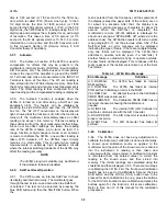
2-6. The 3478A requires a power source of 100V,
120w 220V, or 240V ac (- 10%, + 5%), 48Hz to 440Hz
sing phase. The maximum power consumption is 25VA.
For the 3478A to meet its noise and normal mode
rejection specifications, the multimeter must be operated
using line frequency of either 50Hz or 60Hz (dependent
on instrument option). A listing of the 3478A’s power
options, the corresponding power line voltages and
frequencies, and fuses are as follows:
Option Voltage and Frequency Fuse
Option 315 100V ac @ 50Hz 250mA
Option 316 100V ac @ 60Hz 250OmA
Option 325 120V ac @ 50Hz 250mA
Option 326 120V ac @ 60Hz 250mA
Option 335 220V ac @ 50Hz 125mA
Option 336 220V ac @ 60Hz 125mA
Option 345 240V ac @ 50Hz 125mA
Option 346 240V ac @ 60Hz 125mA
CAUTION
Before connecting power to the
3478A,make sure the power source
matches the power requirements of the
multimeter, as marked on the rear panel
(below the power receptacle). If the
instrument is incompatible with the
available power source, go to paragraph
2-7 to reconfigure the multimeter.
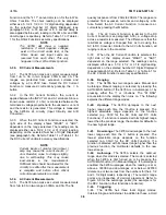
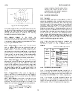
2-7. Line Frequency and Line Voltage Selection
To avoid electrical shock and personal
in- jury, make sure the multimeter is
disconnected from its external power
voltage source before removing any
covers.
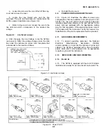
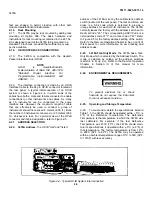
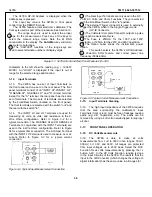
2-8. The Power Line Frequency configuration of the
3478A is done by the 8 section "DIP" switch at the
multimeter’s rear panel. Locate the switch (shown in
Figure 2-1) and set the switch to the desired power
frequency (50Hz or 60Hz), as shown in the figure. To set
the 3478A’s correct line voltage, perform the following
Figure 2-1. Line Frequency Switch
2-1
Содержание 3478A
Страница 2: ...TM 11 6625 3071 14 A ...
Страница 4: ...TM 11 6625 3071 14 C D BLANK ...
Страница 12: ...TM 11 6625 3071 14 Table 1 1 Specification 1 2 ...
Страница 13: ...TM 11 6625 3071 14 Table 1 1 Specifications Cont 1 3 ...
Страница 14: ...TM 11 6625 3071 14 Table 1 1 Specifications Cont 1 4 ...
Страница 53: ...TM 11 6625 3071 14 1 ...
Страница 54: ...TM 11 6625 3071 14 2 ...
Страница 55: ...TM 11 6625 3071 14 3 ...
Страница 56: ...TM 11 6625 3071 14 4 ...
Страница 87: ...TM 11 6625 3071 14 3478A Figure 7 D 3 Flowchart B 7 D 5 ...
Страница 88: ...TM 11 6625 3071 14 3478A Figure 7 D 4 Flowchart C 7 D 6 ...
Страница 91: ...TM 11 6625 3071 14 3478A Figure 7 D 6 Flowchart D 7 D 9 ...
Страница 98: ...TM 11 6625 3071 14 3478A Figure 7 F 2 Simplified Schematic Of The Input Switching Circuitry 7 F 4 ...
Страница 111: ...TM 11 6625 3071 14 Figure 7 F 17 3478A Simplified Reference Circuitry 7 F 16 ...
Страница 122: ...TM 11 6625 3071 14 Table A 2 A 2 HP IB Worksheet A 4 ...
Страница 137: ...TM 11 6625 3071 14 Figure 7 D 2 Flow chart A 7 D 3 ...
Страница 139: ...TM 11 6625 3071 14 Figure 7 G 2 3478A Block Diagram 7 G 3 ...
Страница 140: ...TM 11 6625 3071 14 Component Locator for Input Circuitry and Ohms Current Source 7 G 4 ...
Страница 141: ...TM 11 6625 3071 14 Figure 7 G 3 Input Circuitry and Ohms Current Source 7 G 5 ...
Страница 142: ...TM 11 6625 3071 14 F G 6 ...
Страница 143: ...TM 11 6625 3071 14 2 Figure 7 G 4 AC to DC Converter 7 G 7 ...
Страница 144: ...TM 11 6625 3071 14 Component Locator for A D Converter and Control Logic 7 G 8 ...
Страница 145: ...TM 11 6625 3071 14 3 Figure 7 G 5 A D Converter and Control Logic 7 G 9 ...
Страница 146: ...TM 11 6625 3071 14 7 G 10 ...
Страница 147: ...TM 11 6625 3071 14 4 Figure 7 G 6 Power Supplies 7 G 11 7 G 12 blank ...
Страница 148: ......
Страница 149: ...PIN NO 057444 ...


