background image

TM 11-6625-3071-14

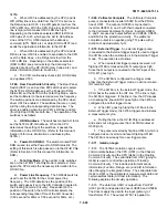
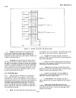
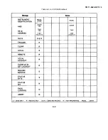
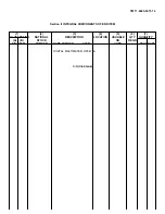
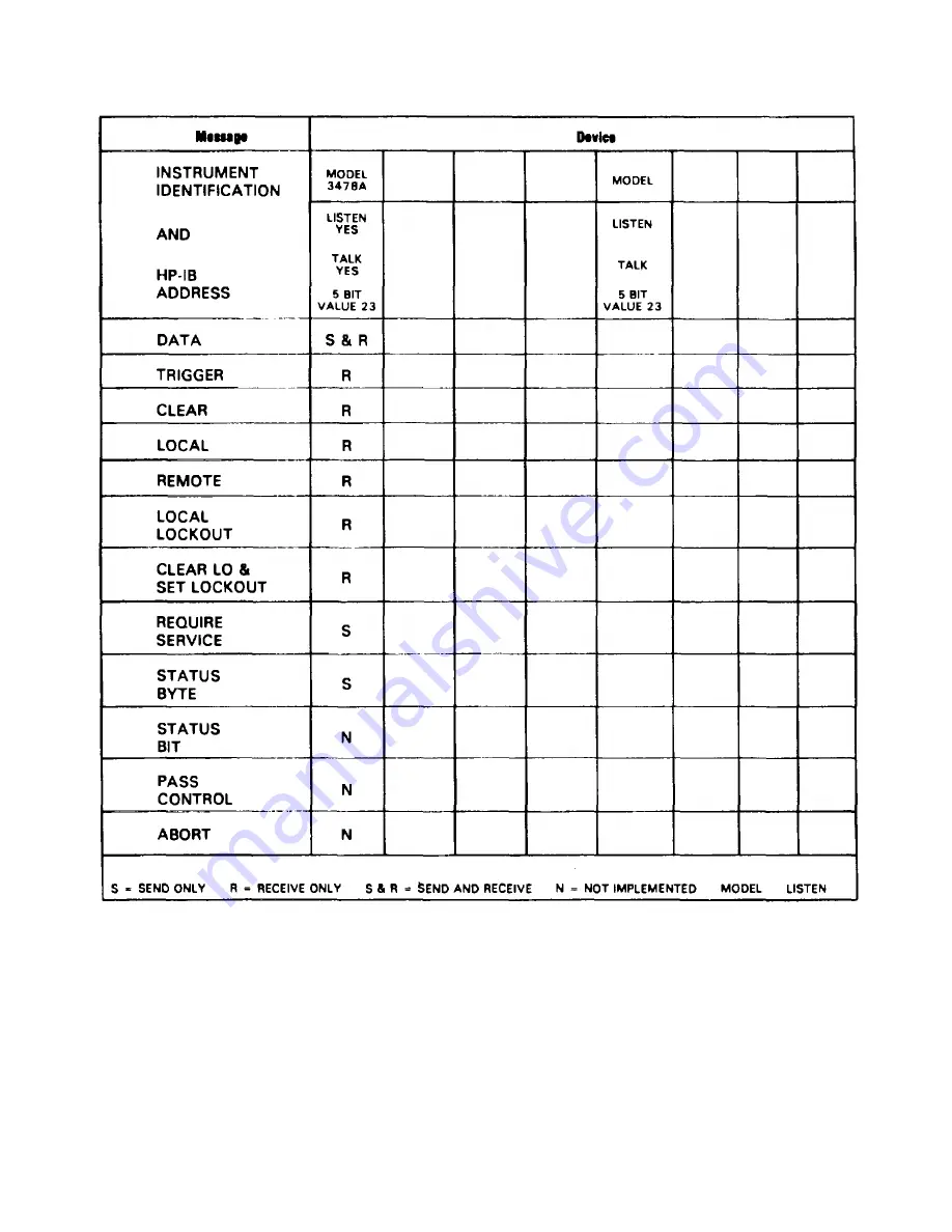
Table A-2. A-2 HP-IB Worksheet

A-4

Содержание 3478A

Страница 1: ... 6625 3071 14 TECHNICAL MANUAL OPERATOR S ORGANIZATIONAL DIRECT SUPPORT AND GENERAL SUPPORT MAINTENANCE MANUAL DILGITAL MULTIMETER HEWLETT PACKARD MODEL 3478A HEADQUARTERS DEPARTMENT OF THE ARMY 5 MARCH 1985 ...

Страница 2: ...TM 11 6625 3071 14 A ...

Страница 3: ... of flammable gases or fumes Operation of any electrical instrument in such an environment constitutes a definite safety hazard KEEP AWAY FROM LIVE CIRCUITS Operating personnel must not remove instrument covers Component replacement and internal adjustments must be made by qualified maintenance personnel Do not replace components with power cable connected Under certain conditions dangerous voltag...

Страница 4: ...TM 11 6625 3071 14 C D BLANK ...

Страница 5: ...e manual adapts it to earlier instruments Where practical backdating information is integrated into the text parts list and schematic diagrams Backdating changes are denoted by a delta sign An open delta a or lettered delta AA on a given page refers to the corresponding backdating note on that page REPORTING ERRORS AND RECOMMENDING IMPROVEMENTS You can help improve this manual If you find any mist...

Страница 6: ...0 1 Scope 0 1 0 2 Consolidated Index of Army Publications and Blank Forms 0 1 0 3 Maintenance Forms Records and Reports 0 1 0 4 Reporting Equipment Improvement Recommendations EIR 0 1 0 5 Administrative Storage 0 1 0 6 Destruction of Army Electronics Materiel 0 1 ii ...

Страница 7: ...s 3 5 3 38 Ranging 3 5 3 43 Triggering 3 5 3 50 Shifted Operation 3 6 3 51 General 3 6 3 54 Number of Digits Displayed 3 6 3 57 Autozero 3 7 3 60 Self Test Reset Operation 3 7 3 63 Calibration 3 7 3 66 Miscellaneous Operations 3 8 3 67 Voltmeter Complete 3 8 3 69 Remote Operation 3 8 3 70 General 3 8 3 74 3478A Response to Bus Messages 3 8 3 92 3478A Addressing 3 10 3 96 Talk Only Mode No Controll...

Страница 8: ... 1 B References B 1 C Components of End Item List C 1 D Additional Authorization List Not Application E Maintenance Allocation E 1 F Expendable Supplies and Material List N A LIST OF TABLES Tables Page 3 1 Shifted Operations 3 6 3 2 3478A Error Messages 3 7 3 3 3478A Bus Capabilities 3 8 3 4 Status Byte Definitions 3 10 3 5 3478A Address Codes 3 11 3 6 3478A Program Codes 3 12 3 7 Binary Status By...

Страница 9: ...7 D 1 US01 ALE Signal 7 D 2 7 D 2 Flowchart A 7 D 3 Figure Page 7 D 3 Flowchart B 7 D 5 7 D 4 Flowchart C 7 D 6 7 D 5 U462 ALE Signal 7 D 8 7 D 6 Flowchart D 7 D 9 7 D 7 JM403 SA Connection 7 D 10 7 F 1 3478A Simplified Block Diagram 7 F 2 7 F 2 Simplified Schematic of the Input Switching Circuitry 7 F 4 7 F 3 Simplified Schematic of the DC Ohms Input Amplifier 7 F 6 7 F 4 Ohms Circuitry Configura...

Страница 10: ...ment Report DISREP SF 361 as prescribed in AR 55 38 NAVSUPINST 4610 33C AFR 75 18 MCO P4610 19D DLAR 4500 15 0 4 REPORTING EQUIPMENT IMPROVEMENT RECOMMENDATIONS EIR If your equipment needs improvement let us know Send us an EIR You the user are the only one who can tell us what you don t like about your equipment Let us know why you don t like the design Put it on an SF 368 Quality Deficiency Repo...

Страница 11: ...s and mechanical parts 1 13 Section VI Backdating 1 14 This section has information which adapts this manual to 3478A s with serial numbers below the ones shown on the title page 1 15 Section VII Service 1 16 The 3478A s Troubleshooting Procedures Theory Of Operation and Schematics are in Section VII The troubleshooting information is in the form of Service Groups which are symptoms oriented i e w...

Страница 12: ...TM 11 6625 3071 14 Table 1 1 Specification 1 2 ...

Страница 13: ...TM 11 6625 3071 14 Table 1 1 Specifications Cont 1 3 ...

Страница 14: ...TM 11 6625 3071 14 Table 1 1 Specifications Cont 1 4 ...

Страница 15: ...6 set for 220V 60Hz Power Source Option 345 set for 240V 50OHz Power Source Option 346 set for 240V 60Hz Power Source Option 907 Front Handle Kit hp Part No 5061 1088 Option 908 Rack Mount Kit includes one rack flange and one extension adapter hp Part No 5061 0072 Option 910 additional set of Operators and Service Manuals 1 29 ACCESSORIES AVAILABLE 1 30 The following is a list of available accesso...

Страница 16: ...ns C stress notify the carrier as well as the Hewlett Packard office Save the shipping material for the carrier s inspection 2 5 POWER REOUIREMENTS 2 6 The 3478A requires a power source of 100V 120w 220V or 240V ac 10 5 48Hz to 440Hz sing phase The maximum power consumption is 25VA For the 3478A to meet its noise and normal mode rejection specifications the multimeter must be operated using line f...

Страница 17: ...ns that are available to provide power to the 3478A The hp part number shown directly below the individual power plug drawing is the part number for the power cord set equipped with the appropriate mating plug for that receptacle If the appropriate power cord is not included with the instrument notify the nearest hp Sales Service office and a replacement will be provided 2 11 GROUNDING REOUIREMENT...

Страница 18: ...lk and listen address of the 3478A is set by the multimeter s address switch located at the rear panel The talk and listen ad dress is a 5 bit code which is selected to provide a unique address for each HP IB instrument The 3478A normally leaves the factory with the address switch set to Decimal Code 23 The corresponding ASCII Code is a listen address code of 7 and a talk code of W Refer to Figure...

Страница 19: ...office Hewlett Packard suggests that you always insure shipments Figure 2 6 3478a Address Switch 2 29 If the original container is not to be used do the following a Wrap the instrument in heavy plastic before placing in an inner container b Place packing material around all sides of the instrument and protect the front panel with cardboard strips c Place the instrument in the inner container in a ...

Страница 20: ...n paragraph 3 66 Title Paragraph Voltmeter Complete 3 67 e Remote Operation paragraph 3 69 Title Paragraph General 3 70 3478A Response to Bus Messages 3 74 3478A Addressing 3 92 Talk Only Mode No Controller 3 96 3478A HP IB Programming 3 98 Advanced programming 3 117 3 4 GENERAL INFORMATION 3 5 AC Power Operation 3 6 Before connecting ac power to the 3478A make sure the power source matches the po...

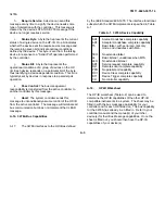
Страница 21: ... switch is in the rear panel terminals are used 8 These keys are used to select special operating features of the 3478A The blue shift key allows for selecting the SHIFTED functions of the bottom row of keys The lnternal Trigger is selected by this key In this mode the 3478A triggers itself Autozeros is a function that allows you to enable or disable the internal zero correction circuitry Pressing...

Страница 22: ...ront panel terminals consist of an INPUT HI Ω INPUT LO Ω SENSE HI Ω SENSE LO and A Amps terminal Except for the A terminal the rear panel has the same set of terminals The two sets of terminals are selected by the Front Rear Switch located on the front panel The front terminals are selected with the switch out and the rear with the switch in 3 14 The INPUT HI and LO Terminals are used for measurin...

Страница 23: ...ragraph 3 54 A 6 second delay is also applied in the ACV Function before a reading is taken also during a range change Refer to Table 1 1 or Table 4 1 for the AC Volts Function s accuracy specifications 3 26 Resistance Measurements 3 27 The 3478A is able to make resistance measurements from 0001 ohms to 30M ohms in seven ranges The ranges extend from the 30 ohm to the 30M ohm range All ranges are ...

Страница 24: ... 3A fuse Select the AC Current Function to measure ac currents by pressing the A button 3 36 The AC Current Function is similar to the DC Current Function see paragraph 3 30 a voltage drop across a resistor is measured The difference is that the resultant ac voltage is changed from ac to dc using the AC to DC Converter Similar to the AC Volts Function all ranging is done in the converter 3 37 When...

Страница 25: ... Trigger except the delays in the ACV and ACI Functions and high Ohms Ranges are omitted This trigger can only be selected using the remote operation NOTE When the 3478A is in the Single Trigger mode and an attempt is made to change range or function the left portion of the display goes blank except for the decimal point until another reading is taken instrument triggered 3 50 SHIFTED OPERATION 3 ...

Страница 26: ...urn on and also when the Self Test is selected The test can be selected by pressing the blue Shift button and then the SGL TRIG button When the test is selected from the front panel all the segments of the display except the upper dots of the colons are on for about five seconds After that the display may indicates a certain message or characters for about 1 4 second When the Self Test is complete...

Страница 27: ...ges paragraph 3 74 Title Paragraph Data 3 76 Trigger GET 3 77 Clear DCL or SDC 3 78 Remote 3 79 Local 3 80 Local Lockout 3 81 Clear Lockout and Set Local 3 82 Require Service SRQ 3 83 Status Byte 3 85 Status Bit 3 89 Pass Control 3 90 Abort 3 91 b 3478A Addressing paragraph 3 92 and Talk Only Mode paragraph 3 96 c 3478A HP IB Programming paragraph 3 98 Title Paragraph General 3 99 Program Codes 3 ...

Страница 28: ...e front panel LOCAL button also places the multimeter in the local state if the button has not been disabled by the Local Lockout Message see next paragraph 3 81 Local Lockout All the front panel buttons are disabled with this message if the 3478A is in remote The message is in effect until cleared over the HP IB or power is cycled 3 82 Clear Lockout and Set Local This message placed the 3478A int...

Страница 29: ... octal number of the example at 125 shown as follows 3 89 Status Bit The 3478A does not respond to a Parallel Poll The Status Bit is used only for Parallel Poll and should not be confused with the bits in the Status Byte Message 3 90 Pass Control The 3478A does not have controller capabilities 3 91 Abort Interface Clear All HP IB communication is terminated including the 3478A s Bus communication ...

Страница 30: ...nd horizontal tab characters are also ignored Other characters which are not included in Table 3 6 cause a Syntax Error bit 2 in the Status Register set In addition a Syntax Error is caused if the characters are sent in a different order than shown in the table e g IF causes a Syntax Error 3 103 Programming the SRQ Mask The SRQ Mask must be set for the 3478A to output a Require Service Message Set...

Страница 31: ...ed by sending program code K and by a device CLEAR message Bit 0 Data Ready is not cleared since it represents the 3478A s current status the bit is cleared when the 3478A outputs its reading Bit 6 is the SRQ bit which can be cleared by a Serial Poll or if the SRQ Mask is set to 00 3 106 Power On SRQ This feature is enabled by setting the Power On SRQ switch to On switch 3 on the rear panel in the...

Страница 32: ... in the output statement except EOI is one byte which adds up to 13 The exponent will be in engineering notation E 3 E 0 E 3 or E 6 and the mantissa will always have I 2 or 3 digits before the decimal point D DDDDD DD DDDD or DDD DDD If the 3478A is in the 4 1 2 or 3 1 2 Digit mode the 5th and or 6th digits will be output as zeroes An overload condition whether plus or minus will be output as 9 99...

Страница 33: ...ne feed The number shows which bit s of the register is true a two digit number can be used since only 6 bits are used by the register For example bits 0 and 5 are true which results in octal 41 the maximum value is 77 Refer to Table 3 7 byte 4 for the definitions of the bits The Error Register is also cleared by sending program code E Table 3 7 Binary Status Byte Definition Byte Definition 1 Bits...

Страница 34: ...ction 1 Year Limits accuracy of reading Number of counts Frequency 300mA Range 3A Range 20Hz 50Hz 1 54 163 2 24 163 50Hz 1KHz 0 81 163 1 5 163 1KHz 10KHz 0 72 163 1 42 163 10KHz 20KHz 0 86 163 1 56 163 4 4 EQUIPMENT REQUIRED 4 5 All the required test equipment for the Performance Tests and Calibration Procedures are listed in Table 4 2 Recommended Test Equipment The equipment used for the individu...

Страница 35: ...idth DC to 100MHz hp Model 1740A T Signature Analyzer hp Model 5004A T P Performance C Calibration T Troubleshooting O Operator s Check a Output from 30mV to 300V dc b Within 005 full scale accuracy c Short term stability better than 0002 per hour 4 10 AC Volts Test and Calibration 4 11 For the AC Volts Test and Calibration AC Volts Function use the Fluke Model 5200A 5215A AC Calibrator If the cal...

Страница 36: ...2 AC DC Current Source The Valhalla Model 2500 is the recommended AC DC Current Source The critical requirements are as follows a Required current is 100mA and IA b Required frequency response is 1KHz and 5KHz c Required accuracy is 03 4 23 AC Calibrator The recommended AC Calibrator is a Fluke Model 5200A Refer to paragraph 4 11 for the critical requirements 4 24 TEST CARDS 4 25 Performance Test ...

Страница 37: ...ature 4 40 The temperature in which the 3478A was last calibrated is called its Reference Temperature To maintain the 3478A s specified accuracy the multimeter must be operated within the specified range of that temperature shown in Table 1 1 If the 3478A is tested or operated outside the temperature range the Temperature Coefficient listed in Table 1 1 must be added to the instrument s specificat...

Страница 38: ...ds to a step in the test procedure Because of this each step number on the test card is shown in parenthesis e g Step 1 in the procedure 4 51 Unless otherwise specified all test signals are applied to the 3478A s HI and LO INPUT Terminals 4 52 Equipment Required The following is the required test equipment for the DC Volts Test Digital Voltmeter hp Model 3456A DC Volts Standard Systron Donner Mode...

Страница 39: ...ure they are within the specified limits i Step 9 Set the 3478A to the 3V Range and set the DC Volts Standard for an accurate output of 300mV Check and record the reading j Step 10 Set the DC Volts Standard for a IV output Check and record the reading k Step 11 Apply IV to the 3478A by reversing the input leads Leave the leads in that position for the next step Check and record the reading l Step ...

Страница 40: ...h step on the test card also corresponds to a step in the procedure with each step number shown in parenthesis in the procedure 4 56 Unless otherwise noted all test signals are applied to the 3478A s A Amps and LO INPUT Terminals 4 57 Equipment Required The following is the required test equipment for the DC Current Test Figure 4 3 DC Common Mode Rejection Test Digital Voltmeter hp Model 3456A DC ...

Страница 41: ... are printed on the Volts Test Card and in Table 4 5 Each step on the card also corresponds to a step in the procedure each step number shown in parenthesis in the procedure 4 61 All test signals are applied to the 3478A s HI LO INPUT Terminals 4 62 Equipment Required The required test equipment for the AC Volts Test is the AC Calibrator F Model 5200A 5215A Option 05 4 8 4 63 Test Procedure Make s...

Страница 42: ...ck and record the reading n Step 23 and 24 Set the 3478A to the 3V Range Check the full scale accuracy of the range by applying 3V at 50Hz and then 3V at 20Hz Leave the AC Calibrator set up for a 3V at 20Hz output Check and record the readings o Step 25 Set the 3478A to the 4 Digit Display mode by pressing the blue Shift button and then the Uprange 4 button Check and record the reading p Disconnec...

Страница 43: ...ms Function A different set of test leads can have different impedances which show up as an ohms test error 4 71 The Ohms Function of the 3478A can be tested using either full scale or 1 3 scale inputs e g 3K ohm or 1K ohm resistors to check the 3K ohm Range Because of this both test limits are in Table 4 7 and on the Ohms Performance Test Card The test step numbers on the Test Card shown in paren...

Страница 44: ...e 300 Range e Connect either a 3012 or 101f Standard Resistor to the INPUT Terminals refer to paragraph 4 71 to determine the resistor value If the 3478A is to be tested in the 2 Wire Ohms Function connect the resistor to the HI and LO INPUT Terminals If the test is to be done in the 4 Wire Ohms Function connect the resistor as shown in Figure 4 7 Figure 4 7 4 Wire Ohms Connection f Check and reco...

Страница 45: ... button and then the LOCAL CAL button l The 3478A again makes a measurement and this time decides that the applied input is 3V The display should now show 3 00000 VDC If the applied voltage is another value like IV for example the display will show the other value 1 00000 VDC m If the exact value of the calibration source is unknown but the source is accurate enough to calibrate the multimeter con...

Страница 46: ... scale and 1 3 scale 4 An AC Volts calibration is attempted when the applied calibration source is other than 3V ac Make sure the calibration source is correct 3V at 1KHz e ACI VAL ERR The multimeter displays this message when it is unable to calculate an AC Current calibration constant after doing the AC Volts Calibration This condition can exist if the calibration constant for the DC Current Fun...

Страница 47: ...full scale inputs by using the procedure in steps e to 1 The only exception is that the DC Volts Standard is set for an output in step i of 300mV instead of 30mV o Step 5 and 6 Remove the Digital Voltmeter and the DC Volts Standard from the 3478A Short the 3478A s HI and LO INPUT Terminals and set the instrument to the 3V Range p Calibrate the 3V Range applying zero and full scale inputs by using ...

Страница 48: ...RO button 8 Remove the DC Volts Standard and Digital Voltmeter from the 3478A and set the multimeter back to the Single Trigger Mode press the SGL TRIG button w Step 20 and 21 Short the 3478A s HI and LOW INPUT Terminals Set the instrument to the 300V Range x Calibrate the 300V Range applying zero and full scale inputs by using the procedure in steps e to I The only exception is that the DC Volts ...

Страница 49: ...ltmeter from the AC DC Current Calibrator and remove the calibrator from the 3478A This completes the 3478A s DC Current Calibration and Test 4 94 AC Volts Calibration and Test 4 95 The AC Volts Function is calibrated using only one calibration source 3V at 1KHz With the 3V AC signal applied the 3478A determines the gain constants by taking a measurement in the 3V Range and 30V Range The measureme...

Страница 50: ...mV 3V 30V and 300V Range by applying 0 3V at 50KHz 3V at 50KHz 30V at 50KHz and 300V at 5OKhz respectively Check the readings p Step 15 Set the 3478A to the 300mV Range Check the full scale accuracy of the range by applying 0 3V at 100KHz Check the reading q Step 16 and 17 Set the 3478A to the 3V Range Check the 1 10 and full scale accuracy of the range by applying 0 3V at 100KHz and 3V at 100KHz ...

Страница 51: ... the reading on the multimeter until it agrees with the output value of the AC DC Current Calibrator if the output value is known k Press the SGL TRIG button once l This completes the AC Current Calibration If a Performance Test is desired continue with the next step Otherwise remove the 3478A and the AC Calibrator from the AC DC Current Calibrator m Step 2 If a Performance Test is desired set the...

Страница 52: ... except use a 3000 or 100 resistor instead of a 30 0 or 100 resistor l Step 5 and 6 Set the 3478A to the 3Kn Range and calibrate the range using zero and full scale or 1 3 scale inputs Use the same procedures in steps d through i except use a 3K or IKO resistor instead of a 30Q or 100 resistor m Step 7 and 8 Set the 3478A to the 30K Range and calibrate the range using zero and full scale or 1 3 sc...

Страница 53: ...TM 11 6625 3071 14 1 ...

Страница 54: ...TM 11 6625 3071 14 2 ...

Страница 55: ...TM 11 6625 3071 14 3 ...

Страница 56: ...TM 11 6625 3071 14 4 ...

Страница 57: ...__ _____ 10 30V 20KHz 300V Range 030 201V _______ 029 799V _____ _____ 11 300V 20KHz 300V Range 301 092V _______ 298 908V _____ _____ 12 0 3V 50KHz 300mV Range 301 927V _______ 298 073V _____ _____ 13 3V 50KHz 3V Range 3 01410V _______ 2 98590V _____ _____ 14 30V 50KHz 30V Range 30 1290V _______ 29 8710V _____ _____ 15 300V 50KHz 300V Range 301 860V _______ 298 140V _____ _____ 16 0 3V 100KHz 300m...

Страница 58: ...____ Reference Temperature__________________ AC Current Test Step Input to Set Up and High Reading Low Test Test 3478A Configuration Limit Limit Pass Fail 1 Open Press TEST RESET 2 Open ACV Function 3 01A 5KHz 300mA Range 010 235mA _______ 009 765mA _____ _____ 4 0 1A 5KHz 300mA Range 100 883mA _______ 099 117mA _____ _____ 5 1A 5KHz 3A Range 1 01583A _______ 0 98417A _____ _____ 6 ...

Страница 59: ...3M Range 0 00002M _______ 0 00000M _____ _____ 8 Short 30M Range 00 0002M _______ 00 0000M _____ _____ 9 30 ohm 30 Range 30 0104 _______ 29 9896 _____ _____ 9 10 ohm 10 0058 _______ 09 9942 _____ _____ 10 300 ohm 300 Range 300 018 _______ 299 982 _____ _____ 10 100 ohm 100 009 _______ 099 991 _____ _____ 11 3K ohm 3K Range 3 00013K _______ 2 99987K _____ _____ 11 1K ohm 1 00006K _______ 0 99994K _...

Страница 60: ...3M Range 0 00002M _______ 0 00000M _____ _____ 8 Short 30M Range 00 0002M _______ 00 0000M _____ _____ 9 30 ohm 30 Range 30 0143 _______ 29 9857 _____ _____ 9 10 ohm 10 0075 _______ 09 9925 _____ _____ 10 300 ohm 300 Range 300 056 _______ 299 944 _____ _____ 10 100 ohm 100 022 _______ 099 978 _____ _____ 11 3K ohm 3K Range 3 00050K _______ 2 99950K _____ _____ 11 1K ohm 1 00018K _______ 0 99982K _...

Страница 61: ...ange 0 00002M _______ 0 00000M _____ _____ 8 Short 30M Range 00 0002M _______ 00 0000M _____ _____ 9 30 ohm 30 Range 30 0122 _______ 29 9878 _____ _____ 9 10 ohm 10 0068 _______ 09 9932 _____ _____ 10 300 ohm 300 Range 300 041 _______ 299 958 _____ _____ 10 100 ohm 100 017 _______ 099 983 _____ _____ 11 3K ohm 3K Range 3 00035K _______ 2 99965K _____ _____ 11 1K ohm 1 00013K _______ 0 99987K _____...

Страница 62: ...rts address order or inquiry to your local Hewlett Packard Office Office Locations are listed at the back of this manual Identify parts by their Hewlett Packard Part Numbers Include instrument model and serial number 5 6 NON LISTED PARTS 5 7 To obtain a part that is not listed include a Instrument Model Number b Instrument Serial Number c Description of the part d Function and location of the part...

Страница 63: ...e Figure 5 4 Loosen and remove the screws on both the left and right side side covers MP4 Remove the covers f Refer to Figure 5 5 Loosen and remove screws MP21 on the bottom plastic shield MP23 Remove the shield g Refer to Figure 5 4 Loosen and remove screws MP17 on the left side frame of the 3478A h Refer to Figure 5 4 Loosen and remove screws MP17 at the 3478A s side frames on both the left and ...

Страница 64: ...28480 0160 4571 A1C433 0160 4571 B CAPACITOR FXD 1UF 80 20 50VDC CER 28400 0160 4571 A1C463 0160 3847 9 4 CAPACITOR FXD 01UF 100 0 50VDC CER 28480 0160 3847 A1C464 0160 3847 9 CAPACITOR FXD 01UF 100 0 50VDC CER 28480 0160 3847 A1C465 0160 4807 4 CAPACITOR FXD 33PF 5 100VDC CER 0 30 28480 0160 4807 A1C466 0160 4807 3 CAPACITOR FXD 33PF 5 100VDC CER 0 30 28480 0160 4807 A1C467 0160 4571 8 CAPACITOR ...

Страница 65: ... 1 SOCKET IC 16 C0NT DIP DIP SLDR 28480 1200 0853 A1JM403 1258 0141 8 4 JUMPER REM 28480 1258 0141 A1JM501 1258 0141 8 JUMPER REM 29480 1258 0141 A1JM502 1258 0141 8 JUMPER REM 28480 1258 0141 A1JM503 1258 0141 8 JUMPER REM 28480 1259 0141 A1K101 0490 1310 6 1 RELAY REED CR 2583 28480 0490 1310 A1K102 0490 1309 3 3 RELAY REED CR 2584 28480 0490 1309 A1K103 0490 1309 3 RELAY REED CR 2584 28480 0490...

Страница 66: ...83 5125 8 RESISTOR 5 1K 5 25W FC TC 400 700 01121 CB5125 A1R531 0683 5125 8 RESISTOR 5 1K 5 25W FC TC 400 700 01121 CB5125 A1R532 0683 5125 8 RESISTOR 5 1K 5 25W FC TC 400 700 01121 CB5125 A1R534 0686 1015 3 2 RESISTOR 100 5 5W CC TC 0 529 01121 EB1015 A1R538 0606 1015 3 RESISTOR 100 5 5W CC TC 0 529 01121 EB1015 A1R539 0683 5125 8 RESISTOR 5 1K 5 25W FC TC 400 700 01121 CB5125 A1R540 0683 5125 8 ...

Страница 67: ...702 4 1 IC NMOS 16384 BIT PROM 28480 1820 2702 A1U508 1820 1199 1 1 IC INV TTL LS HEX 1 INP 01295 SN74LS04N A1U510 1820 1794 2 1 IC BFR TTL LS NON INV OCTL 27014 DM81LS95N A1U512 1818 1754 9 1 IC RAM MOS 5101L 28480 1818 1754 A1U513 1820 2102 8 1 IC LCH TTL LS D TYPE OCTL 01295 SN74LS373N A1U514 1820 1212 9 1 IC FF TTL LS J K NEG EDGE TRIG 01295 SN74LS112AN A1U515 1520 1144 6 IC GATE TTL LS NOR QU...

Страница 68: ...760 03478 61901 6 1 POWER SWITCH ASSY 28480 03478 61901 U760 1826 0536 0 1 IC 340A V RGLTR TO 3 27014 LM340AK 5 MISCELLANEOUS PARTS F101 2110 0003 0 1 FUSE 3A 250V NTD 1 25X 25 UL 75915 312003 SI 03478 61902 7 1 FRONT REAR SWITCH ASSY 28480 03478 61902 W502 8120 3280 8 1 CABLE ASSY 28 PVCRBN 28480 8120 3280 03478 60201 7 1 FRONT PANEL ASSEMBLY 28480 03478 60201 5001 1872 5 1 DISPLAY LCD 28480 5001...

Страница 69: ...r MP11 5040 7201 8 4 Feet MP12 1460 1345 4 2 Tilt Stand MP13 5020 8813 8 1 Front Frame MP14 03478 61201 9 2 Side Frame MP15 2510 0192 6 8 Screw MP16 5001 0438 7 2 Trim MP17 0515 0212 9 7 Screw MP18 5020 8814 9 1 Rear Frame MP19 0403 0164 3 6 Guide PC Board MP20 0515 0211 8 4 Screw MP21 051 5 021 7 5 2 Screw Plastic Shield MP21 3050 0222 8 2 Washer Plastic Shield MP22 7120 8607 2 1 Metric Label MP2...

Страница 70: ...ction has information which adapts this manual to instruments with serial numbers below the ones shown on the title page Since this manual does directly apply to instruments having serial numbers listed on the title page no change information is given here 6 1 6 2 blank ...

Страница 71: ...ltage is applied should be avoided as much as possible If any work is done while power and or voltage is applied the work should be carried out by a skilled person who is aware of the hazards involved WARNING Any interruptions of the protective grounding conductor inside or outside the instrument or disconnections of the protective earth terminal can make the instrument dangerous Intentional inter...

Страница 72: ...RAM has failed its internal self test The failure is normally caused by a defective U501 To make sure U501 is the cause go to Service Group D paragraph 7 D 21 for further troubleshooting 7 21 Control ROM Fails U C ROM FAIL This indicates that the 3478A has failed its internal ROM self test The Control ROM U502 is the most likely cause Go to Service Group D paragraph 7 D 19 for further troubleshoot...

Страница 73: ...normally caused when the AC to DC Converter has poor frequency response c Floating Reading A floating reading is when the 3478A displays a certain reading with no input applied which does not change after an input is applied to the multimeter This can be caused if there is an open circuit in the AC to DC Converter or A D Converter d Noisy Readings Noisy readings can be caused by the amplifiers and...

Страница 74: ...lso be caused by other circuitry in the Chassis Common Logic Circuitry 7 34 Floating Common Logic Failures Service Group D Floating Common Logic Failures are normally caused by the A D Converter or the A D Controller U462 Go to Service Group D paragraph 7 D 31 for troubleshooting The following explains the failures a Overload Constant Zero Floating or Noisy Readings Any one of these failures can b...

Страница 75: ... g U102 which are extremely susceptible to failures due to static discharge It is especially important that grounded tools and wrist straps be used when handling or troubleshooting these components 7 A 3 PRE TROUBLESHOOTING INFORMATION 7 A 4 Before doing any troubleshooting procedures perform the following a Check the 3478A s Floating Common Power Supplies and make sure they are stable have the co...

Страница 76: ...e hybrid is also used to select the amplifier s different gain configurations Because of this a relay or U102 can make certain ranges fail 7 A 13 Overload An overload condition exists if the DC Ohms Input Amplifier s feedback circuitry is open Since the feedback circuitry is in U102 the hybrid is most likely defective Before replacing U102 make sure the A D Controller U462 is good Go to paragraph ...

Страница 77: ... are not shorting to ground If no shorts are noted do the following a Set the 3478A to the DC Volts Function and the 3V Range b Make sure Autozero is turned off see paragraph 7 A 8 step b c Using an external power supply with a 100K ohm resistor in series apply 3V to pin 3 of U101 Connect one end of the resistor to pin 3 of U101 and the other end to the power supply d Using a high impedance Digita...

Страница 78: ... troubleshoot for DC Volts Failures If the DC Volts Function is good the only components that can cause a current failure are an open current fuse F101 a defective resistor R107 or the Input Hybrid U102 Make sure F101 and R107 are good If the resistor and fuse are good U102 may be defective Before replacing U102 make sure the A D Controller U462 is good Go to paragraph 7 A 33 to check the A D Cont...

Страница 79: ...ting procedures go to paragraph 7 31 for a description of these failures Unless otherwise specified refer to Schematic 2 for the following troubleshooting procedures 7 B 5 Overload Floating or Noisy Readings on All Ranges 7 B 6 An overload reading can be caused if one of the amplifiers or the RMS Converter in the AC to DC Con verter is saturated A floating reading can be caused if there is an open...

Страница 80: ... to DC Converter is done in the Input Hybrid U102 the hybrid is the most likely cause for ac failures on some ranges Before replacing U102 make sure it is not set to an incorrect mode by the A D Controller U462 Go to paragraph 7 B 16 to check the A D Controller If the controller is good replace U102 7 B 12 AC CURRENT TROUBLESHOOTING 7 B 13 Make sure the DC Current and AC Volts Functions are operat...

Страница 81: ...ounded tools and wrist straps be used when handling or troubleshooting these components 7 C 4 2 WIRE AND 4 WIRE OHMS TROUBLE SHOOTING 7 C 5 An Ohms Failure can be Overload Inaccurate Constant Zero Floating or Noisy Readings on some or all ranges A failure should show up with an appropriate input applied to the 3478A For example an overload failure on the 3K ohm Range should show up with a 3K ohm r...

Страница 82: ...t zero reading the Ohms Current Source is inoperative Go to paragraph 7 C 20 for troubleshooting e If the Ohms Function is now operating correctly do the following 1 Disconnect the clip lead from pin 15 of U102 and connect it to the collector of Q204 junction of Q204 R203 and cathode of CR201 Leave the other end of the clip lead connected to the input terminal for the checks that follow 2 If the O...

Страница 83: ... at that level 6 If the voltage does not go to 0V replace CR201 7 If the voltage does go to 0V the Ohms Protection Circuitry does protect for positive input voltages b To check the circuitry operation for negative input voltages do the following 1 Leave the same set up as in step a except bring the variable power supply down to 0V The voltage across R205 should again be 47V 2 Reverse the power sup...

Страница 84: ...E Terminals and a different input path in U102 Make sure the Front Rear Switch is good and that the wires from the terminals are connected correctly Also make sure the lead resistance of the test used in the 4 Wire Ohms Function is not excessive 1 30 of full scale reading in the LO INPUT lead and 1 3 of full scale in the HI INPUT lead If everything appears to be good U102 may be defective Before r...

Страница 85: ...ay Keyboard and associated circuitry Its purpose is to control the operation of the instrument The Floating Common Logic Circuitry consists of an A D Controller U462 A D Converter U403 U401 etc and associated circuitry Its purpose is to control the A D conversion and to control the Input Hybrid Com munications between the circuitry are done by the Isola tion Circuitry 7 D 4 Most of the procedures ...

Страница 86: ...rs JMS01 JM502 and JM503 are in the N Normal position The 3478A will not turn on at all or properly if they are in a different position 7 D 13 Inoperative Display 7 D 14 An inoperative display is when all or part of the display is inoperative The failure can be caused by the display itself or part of the Chassis Common Circuitry Before doing any troubleshooting make sure the 1 IV 2 2V and 3 3V pow...

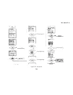
Страница 87: ...TM 11 6625 3071 14 3478A Figure 7 D 3 Flowchart B 7 D 5 ...

Страница 88: ...TM 11 6625 3071 14 3478A Figure 7 D 4 Flowchart C 7 D 6 ...

Страница 89: ...aused by a defective U514 or HP IB Chip Do the following a Set the 3478A to the Single Trigger mode b Using a logic probe make sure pin 5 of U514 is high If the pin 1s low do the following 1 Check for a low at pin 4 of U514 2 If pin 4 of U514 is low replace U514 3 If pin 4 of U514 is high replace U503 c If pin 5 of U514 is high using a logic pulser pulse i e toggle pin 5 d Using a logic probe chec...

Страница 90: ...n the Flowchart checks the different ports using Signature Analysis of the A D Controller U462 and also checks the DAC U465 7 D 39 A D Test Falls If the message A D TEST FAIL is displayed the A D Converter fails its internal test Since this can be caused by the A D Controller U403 and associated circuitry or the A D Controller U462 go to Flowchart D for troubleshooting The procedure in the Flowcha...

Страница 91: ...TM 11 6625 3071 14 3478A Figure 7 D 6 Flowchart D 7 D 9 ...

Страница 92: ...478A s chassis The LO INPUT terminal can be used as a Floating Common ground make sure the cor rect terminal is used dependent on the position of the Front Rear Switch d Connect and set the Signature Analyzer as follows Start U462 pin 1 Stop TP8 Clock TP3 Hold Out Self Test Out Gnd Chassis Ground e Turn the 3478A on and check the signature of the Chassis Common 5V power supply f If the signature i...

Страница 93: ...d by a defec tive U701 7 E 10 15V and 1SV Supplies Since the 15V supp ly is a mirror image of the 15V supply use the following procedure for both supplies The only difference is that the 15V supply has an additional filter capacitor C706 E 11 A low supply can be caused by an excessive load on the supply a shorted filter capacitor or protec tion diode an open temperature sensitive resistor RT706 or...

Страница 94: ...now good replace U102 If still wrong continue with the next step d If the buffered 10V is wrong or noisy do the following 1 Check for a quiet 10V at pin 2 of U402 2 If the voltage is wrong replace U403 3 If the voltage is good connect pin 19 to pin 24 of U403 4 If the voltage at pin 6 of U402 is now at 10V replace U403 If not replace U402 7 E 2 ...

Страница 95: ... ROM and associated circuitry Communications between the Chassis Common and Floating Common is done by the Isolation Circuitry 7 F 6 The following paragraphs explain a typical measurement sequence a Set up The 3478A receives range and function in formation from the front panel local or over the HP IB remote The information is received by the Main Controller which then passes the information over t...

Страница 96: ...rter The A D Converter changes the voltage to digital information and applies it to the A D Con troller The A D Controller passes it on to the main controller which calculates the correct reading using the zero measurement see step f and calibration constant s e AC Current or DC Current Function If the AC Current or DC Current Functions are selected the input current is applied to resistor R107 1 ...

Страница 97: ... on each node are connected internally in U 102 to 3 5V and 3 5V power supplies If the voltage on a node exceeds either 4 2V or 4 2V a diode conducts and keeps the level on the node to the 4 2V levels The difference between the high voltage at the input ter minals and the voltage at the input nodes is dropped across the resistors which are in series with the diodes and input terminals the low pass...

Страница 98: ...TM 11 6625 3071 14 3478A Figure 7 F 2 Simplified Schematic Of The Input Switching Circuitry 7 F 4 ...

Страница 99: ...nd Note MOSFET switches S6ADC S6BDC and S6CDC are in U102 7 F 15 Pre Charge Stage Figure 7 F 21 A small stray capacitance exists in U102 between the input of the DC Ohms Input Amplifier and ground During a zero measurement measure zero in the Autozero Function this capacitor is at zero volts After the zero measure ment the input to the 3478A is applied to the Input Amplifier and the capacitor is c...

Страница 100: ...he positive terminal of Buffer U202 The reference out put which is applied to the positive terminal of the Out put FET Control Amp U203 is divided down to 8V irrespective of range by feedback resistors RR3 and RR4 in conjunction with R206 b The output of the Buffer is 12V or 8 4V for the 30M ohm Range only which is applied to one side of either Range Resistor RRS RR6 RR7 or RR8 dependent on the se...

Страница 101: ... Refer to Table 7 F I to determine which switch and resistor is selected for the different ohms ranges 7 F 23 The Output FET Control Amplifier U203 and the Output MOSFET in U102 form a feedback circuit used to boost the output impedance of the Output MOSFET The FET is normally biased into saturation and in conjunction with the open loop gain of U203 and the Range Resistors results in a high output...

Страница 102: ... 2 for the following explanation a The first amplifier stage U301A is an inverting amplifier with gains of X 00 X 1 or XI dependent on the ac range and function selected The gains are deter mined by resistors RAI RA2 RA3 and RAII all in U102 as shown in Figure 7 F 5 Capacitor C302 and resistor R305 are used for high frequency compensation for flat gains at high frequency The gain determining resis...

Страница 103: ...nsists of an Integrator U401 and associated circuitry Voltage Reference U461 and associated circuitry and the A D Hybrid U403 The A D Converter operation is controlled by the A D Controller U462 7 F 33 The A D conversion method used by the 3478A is called Multi Slope II and has two operating states Runup and Rundown The 3478A s most significant digits are determined during runup see paragraph 7 F ...

Страница 104: ... d When time T3 is completed the A D Controller determines if the output slope crossed zero If zero crossing is detected a current with the same value and an opposite polarity as the previously applied current is applied This current is the same current as the first applied current and is applied to the integrator for a new time period T4 T4 is as long as T3 This current in addition to the input c...

Страница 105: ...re generated differently see paragraph 7 F 39 Slope S O is selected since the previous no current condition was slope S 0 The slopes alternate with each other S 0 S O S 0 etc for each no current condition e When time T2 is completed an S 4 current is applied for 30 ALE cycles 36 ALE cycles for the 50Hz option during time period T3 The S 4 current has the same value as S 4 but at opposite polarity ...

Страница 106: ...K ohm Figure 7 F 11 Slope S 4 Generation resistor and paths Y1 and Y2 to Vref Current also flows from the integrator capacitor C to Vref This current is generated because the total resistance of the Y1 and Y2 paths is smaller than the 100K ohm resistor from Vref The current from Vref plus the current from the capacitor equals the total current through paths Y1 and Y2 Since the total resistance of ...

Страница 107: ... with its amplitude and polarity dependent on the last current applied S 4 or S 4 and the input voltage applied during runup By obtaining the value of the remaining voltage the least significant digits can then be determined The voltage value is obtained by applying various currents to the integrator and counting the number of of times the currents have to be applied for the resultant output slope...

Страница 108: ... T4 g The next current applied is negative S 1 This cur rent is 1 10 the value of S 2 1 1000 of S 4 and in the opposite direction The current is applied until it crosses zero The currents are also removed within 15 ALE cycles after slope S I crosses zero h Once the S I currents are removed a positive S I current is applied for 5 ALE cycles and is called one sixth ramp This current is applied inste...

Страница 109: ...U404 U402 and associated cir cuitry uses part of the A D Hybrid for stability pur poses and since it is also used by the A D Converter it is considered part of the converter circuitry Refer to Schematic 3 for the following explanation on the A D Converter Circuitry except for the DAC see paragraph 7 F 46 and 7 F47 for its explanation a A D Hybrid U403 The A D Hybrid shown in Figure 7 F 16 operates...

Страница 110: ...Converter This includes the control of the runup and rundown operation and selecting the correct currents S 4 S 4 etc Refer to paragraph 7 F 77 for more information on the A D Controller d Voltage Reference The Voltage Reference provides three stable reference voltages 10 OV 10V and a buffered IOV The circuitry shown in Figure 7 F 17 is explained as follows 1 The O1V reference voltage is used by t...

Страница 111: ...TM 11 6625 3071 14 Figure 7 F 17 3478A Simplified Reference Circuitry 7 F 16 ...

Страница 112: ... clock is determined by 5 865 MHz crystal Y5O1 b The Data Lines DO to D7 from the CPU are used as both Data Lines and the lower 8 bits of the Address Lines AO to A7 This is done by multiplexing the lines The Address Lines are used to address the Control ROM CMOS RAM and the HP IB Chip The Data Lines send and receive data between the CPU and the Control ROM CMOS RAM and HP IB Chip The ALE Address L...

Страница 113: ...s scanned The reset pulse is developed from P15 using C501 and R528 3 If the TEST RESET button is pressed or the CPU goes to a non operational state the keyboard scanning is stopped 4 Since the ALE clock is still operating the counter keeps incrementing for about 1 3 seconds 5 After the 1 3 seconds the Q output of U507 goes high RESET REQ line goes high This is because the counter is not being res...

Страница 114: ...P17 U501 pins 31 to 34 b Before scanning starts Ports P14 to P17 are low When scanning begins starting with Port P14 each port goes sequentially high c During the time that the keyboard is scanned the CPU determines which one and if any of Ports P0O to P13 are high A high on P10 to P13 is used to determine the button pressed For example the SRQ button is pressed and turns the corresponding SRQ swi...

Страница 115: ...e position of the switch the A D Controller selects the corresponding Integration Time of the A D Converter 1 60 second for 60Hz or 1 50 second for 50Hz etc 7 F 69 Voltmeter Complete The Voltmeter Complete pulse is connected to inverter U508C from the PROG line of U501 The output of U508C is connected to inverters U508D E and F with their outputs connected to the Voltmeter Complete Terminal Invert...

Страница 116: ...Converter CMP the Comparator Output is applied to the Ti input of the CPU at U462 pin 1 The ALE output Address Latch Enable at U462 pin 11 is used as the converter s clock Refer to paragraph 7 F 31 for more information on the A D operation 7 F 79 Input Hybrid Control The control lines to the Input Hybrid U102 which come from Ports P15 to P17of the CPU and are Data Mode and Clock The lines do the f...

Страница 117: ...ent RT706 heats up b Since RT706 and RT707 have positive temperature coefficients their resistance increases to a large value due to high temperature c The high resistance causes most of the supply voltage to drop across RT706 and RT707 shutting down the respective supply d The large resistance value remains until RT706 or RT707 cool down the supply draws normal current 7 F 86 5V Power Supply Floa...

Страница 118: ...atic 1 7 G 3 AC to DC Converter Schematic 2 7 G 4 A D Converter and Control Logic Schematic 3 7 G 5 Power Supplies Schematic 4 7 G 6 7 G 1 INTRODUCTION 7 G 2 This Service Group has the 3478A s Block Diagram and Schematics In addition general schematics notes are also included to gain an under standing on how to use the schematics Figure 7 G 1 General Schematic Notes 7 G 1 7 G 2 blank ...

Страница 119: ...e remaining five GENERAL INTERFACE MANAGEMENT lines are used to manage the devices on the HP IB This includes activating all connected devices at once clearing the interface and others A condensed description is available in the Condensed Description of the Hewlett Packard Interface Bus Manual hp part number 59401 90030 The manual is available through your local hp Sales and Service Office A 9 HP ...

Страница 120: ...tion specified by the controller and the information that comprises the messages The second part can be classified as HP IB management messages These message are comprised of twelve messages and are called Bus messages a Data The actual information binary bytes sent by a talker to one or more listener The information data can either be in numeric form or a character string b Trigger The Trigger me...

Страница 121: ...the active controller The message will terminate all bus communication but does not implement the CLEAR message A 16 3478A Bus Capabilities A 17 The 3478A interfaces to the HP IB as defined by the IEEE Standard 488 1978 The interface functional subset which the 3478A implements is specified in Table A 1 Table A 1 3476A Device Capability SH1 Source Handshake complete capability AH1 Acceptor Handsha...

Страница 122: ...TM 11 6625 3071 14 Table A 2 A 2 HP IB Worksheet A 4 ...

Страница 123: ...aintenance Management System TAMMS TM 11 6625 3071 24P Organizational Direct Support and General Support Maintenance Manual Including Repair Parts and Special Tools List for Digital Multimeter HP Model 3478A TM 750 244 2 Procedures for Destruction of Electronics Materiel to Prevent Enemy Use Electronics Command B 1 B 2 blank ...

Страница 124: ...is divided as follows 1 Figure number Indicates the figure number of the illustration on which item is shown 2 Item number The number used to identify item called out in the illustration b National Stock Number Indicates the National Stock Number assigned to the item and which will be used for requisitioning c Description Indicated the Federal item name and if required a minimum description to ide...

Страница 125: ...tity Required Qty Reqd This column lists the quantity of each item required for a complete major item g Quantity This column is left blank for use during the inventory Under the Revd column list the quantity you actually receive on your major item The Date columns are for your use when you inventory the major item C 2 ...

Страница 126: ...tion II INTEGRAL COMPONENTS OF END ITEM 1 2 3 4 5 6 7 ILLUSTRATION NATIONAL DESCRIPTION LOCATION USUABLE QTY QUANTITY A B STOCK ON REQD FIG ITEM NUMBER PART NUMBER FSCM CODE RCVD DATE DIGITAL MULTIMETER HP3478A C 3 C 4 blank ...

Страница 127: ...o detect incipient failure by measuring the mechanical or electrical characteristics of an item and comparing those characteristics with prescribed standards c Service Operations required periodically to keep an item in proper operating conditions ie to clean decontaminate to preserve to drain to paint or to replenish fuel lubricants hydraulic fluids or compressed air supplies d Adjust To maintain...

Страница 128: ...ms such as fuses lamps or electron tubes j Overhaul That maintenance effort service action necessary to restore an item to a completely serviceable operational condition as prescribed by maintenance standards i e DMWR in appropriate technical publications Overhaul is normally the highest degree of maintenance performed by the Army Overhaul does not normally return an item to like new condition k R...

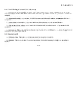
Страница 129: ...enance categories appropriate work time figures will be shown for each category The number of task hours specified by the work time figure represents the average time required to restore an item assembly subassembly components module end item or system to a serviceable condition under typical field operating conditions This time includes preparation time trouble shooting time and quality assurance...

Страница 130: ...r test equipment c Nomenclature This column lists the noun name and nomenclature of the tools and test functions d National NATO Stock Number This column lists the National NATO Stock Number of the specific tool or test equipment e Tool number This column lists the manufacturer s part number of the tool followed by the Federal Supply Code for manufacturers 5 digit in parentheses D 5 Remarks Sec IV...

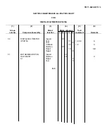
Страница 131: ...roup Maint Maint category Tool number Component assembly function C O F H D equipment Remarks 00 DIGITAL MULTIMETER Inspect 0 1 HP3478A Test 0 1 1 4 6 9 A Test 0 5 Calibrate 0 3 1 9 A Replace 0 1 Repair 1 0 A B Repair 4 0 01 MOTHERBOARD PCB Inspect 0 1 03478 66501 Replace 0 5 C A1 Repair 4 0 Test 1 0 D 5 ...

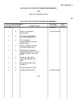
Страница 132: ...ER REF CODE NUMBER 1 H DIGITAL VOLTMETER 6625 00 022 7894 AN GSM 64B 2 H DC VOLTAGE STANDARD SYSTRON DONNER M107 3 H AC CALIBRATOR FLUKE MODEL 5200A AND MODEL 5215A 4 H AC DC CURRENT SOURCE VALHALLA MODEL 2500 5 H RESISTANCE STANDARD REFERENCE PAGE 4 2 OF THE VENDOR MANUAL FOR THIS UNIT 6 H DESKTOP COMPUTER HP85 9825 9826 9835 OR 9845 7 H BUS SYSTEM ANALYZER HP59401A 8 H OSCILLOSCOPE HP1749A 9 H S...

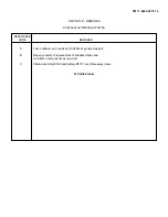
Страница 133: ...ETER HP3478A REFERENCE CODE REMARKS A Test calibrate and repair by USATSG at general support B Repair consists of replacement of subassemblies and mainframe components as required C Cable assembly W502 and battery BT701 are throw away items D 7 D 8 blank ...

Страница 134: ...ary of the Army JOHN A WICKHAM JR General United States Army Official Chief of Staff DONALD J DELANDRO Brigadier General United States Army The Adjutant General Distribution To be distributed in accordance with special list ...

Страница 135: ...TM 11 6625 3071 14 Figure 5 1 3478A Front Panel View Figure 5 2 3478A Rear Panel View Figure 5 3 3478A Bottom View Figure 5 4 3478A Left Side View 5 9 5 10 blank ...

Страница 136: ...TM 11 6625 3071 14 Figure 5 5 Bottom View with Cover Removed Figure 5 6 Top View with Cover Removed Figure 5 7 Front Panel Bracket View Figure 5 8 Front Panel Assembly 5 11 5 12BLANK ...

Страница 137: ...TM 11 6625 3071 14 Figure 7 D 2 Flow chart A 7 D 3 ...

Страница 138: ...e the ROM is defective and not the Main Controller go to Flowchart A see paragraph 7 D 11 for troubleshooting 7 D 21 U C RAM Fails 7 D 22 If the U C RAM FAIL message is displayed the failure is most likely in the Chassis Common CPUs RAM RAM in Main Controller U501 To make sure the RAM is defective go to Flowchart A see paragraph 7 D 11 for troubleshooting 7 D 23 Calibration RAM Failure 7 D 24 If t...

Страница 139: ...TM 11 6625 3071 14 Figure 7 G 2 3478A Block Diagram 7 G 3 ...

Страница 140: ...TM 11 6625 3071 14 Component Locator for Input Circuitry and Ohms Current Source 7 G 4 ...

Страница 141: ...TM 11 6625 3071 14 Figure 7 G 3 Input Circuitry and Ohms Current Source 7 G 5 ...

Страница 142: ...TM 11 6625 3071 14 F G 6 ...

Страница 143: ...TM 11 6625 3071 14 2 Figure 7 G 4 AC to DC Converter 7 G 7 ...

Страница 144: ...TM 11 6625 3071 14 Component Locator for A D Converter and Control Logic 7 G 8 ...

Страница 145: ...TM 11 6625 3071 14 3 Figure 7 G 5 A D Converter and Control Logic 7 G 9 ...

Страница 146: ...TM 11 6625 3071 14 7 G 10 ...

Страница 147: ...TM 11 6625 3071 14 4 Figure 7 G 6 Power Supplies 7 G 11 7 G 12 blank ...

Страница 148: ......

Страница 149: ...PIN NO 057444 ...

Страница 150: ...did not create it They did not even scan it Why should they get your money Why are not letting you give those free manuals to your friends I am setting this document FREE This document was made by the US Government and is NOT protected by Copyright Feel free to share republish sell and so on I am not asking you for donations fees or handouts If you can please provide a link to liberatedmanuals com...

Отзывы: