TM 11-6625-3071-14
SERVICE GROUP F
THEORY OF OPERATION
Service Group F Contents
Title
Paragraph
Introduction ............................................................ 7-F-1
General Block Diagram Theory Of Operation........ 7-F-3
Theory Of Operation .............................................. 7-F-7
General ............................................................... 7-F-8
Input Circuitry.................................................... 7-F-10
Ohms Current Source....................................... 7-F-17
AC to DC Converter.......................................... 7-F-25
A/D Converter ................................................... 7-F-31
3478A Logic Circuitry........................................ 7-F-50
Chassis Common Circuitry ............................... 7-F-55
Isolation Logic................................................... 7-F-71
Floating Common Circuitry ............................... 7-F-75
Power Supplies................................................. 7-F-83
7-F-1. INTRODUCTION
7-F-2. The following Service Group has the general and
detailed description of the operating circuitry of the -hp-
Model 3478A Multimeter. The general description ex-
plains the purpose of each operating block of the 3478A
Simplified Block Diagram (shown in Figure 7-F-I). The
detailed description explains the circuitry in each
operating block.
7-F-3. GENERAL BLOCK DIAGRAM THEORY OF
OPERATION
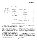
7-F-4. Refer to Figure 7-F-1 for the following discussion
of the 3478A’s General Block Diagram Theory Of
Operation.
7-F-5. The 3478A can be separated into two major
areas, Floating Common and Chassis Common. The
Floating Common has the cicuitry which does the ac, dc,
and ohms measurements. It consists of the Input
Circuitry, A/D Converter, A/D Controller, Ohms Cur- rent
Source, and AC to DC Converter. The Chassis
Common is used to calculate and display readings,
controls the Floating Common Circuitry, and sends and
receives remote information. It consists of the Main
Controller (the main CPU used with the Control ROM)
and associated circuitry. Communications between the
Chassis Common and Floating Common is done by the
Isolation Circuitry.
7-F-6. The following paragraphs explain a typical
measurement sequence.
a.
Set-up. The 3478A receives range and function
in- formation from the front panel (local) or over the
HP-IB (remote). The information is received by the Main
Controller which then passes the information over the
Isolation Circuitry to the A/D Controller. The A/D
Controller then sets up the measurement circuitry to do
the desired measurement. The Main Controller also
sends information to the display to show the selected
function and range. The following takes place in the
3478A’s different functions.
b. DC Volts Function. The following occurs if the
DC Volts Function is selected.
1. The Input Circuitry is set up to a certain gain
configuration by the A/D Controller circuitry. The gain
depends on the range selected.
2. The input voltage is amplified or attenuated
(dependent on the range) to IOV (for full scale in- puts)
which is then applied to the A/D Converter.
3. The A/D Converter changes the voltage to
digital information and transfers it to the A/D Controller.
The A/D Controller then processes the information and
transfers it over the isolation transformers to the Main
Controller.
4. The Main Controller takes the information and
calculates the correct reading. The correct reading is
calculated by using the zero measurement (see step f)
and the calibration constant(s) (which are stored in the
Calibration RAM).
5. The corrected reading is then sent to the front
panel to be displayed and sent over the HP-IB (if the
3478A is in remote and addressed to talk).
7-F-1
Содержание 3478A
Страница 2: ...TM 11 6625 3071 14 A ...
Страница 4: ...TM 11 6625 3071 14 C D BLANK ...
Страница 12: ...TM 11 6625 3071 14 Table 1 1 Specification 1 2 ...
Страница 13: ...TM 11 6625 3071 14 Table 1 1 Specifications Cont 1 3 ...
Страница 14: ...TM 11 6625 3071 14 Table 1 1 Specifications Cont 1 4 ...
Страница 53: ...TM 11 6625 3071 14 1 ...
Страница 54: ...TM 11 6625 3071 14 2 ...
Страница 55: ...TM 11 6625 3071 14 3 ...
Страница 56: ...TM 11 6625 3071 14 4 ...
Страница 87: ...TM 11 6625 3071 14 3478A Figure 7 D 3 Flowchart B 7 D 5 ...
Страница 88: ...TM 11 6625 3071 14 3478A Figure 7 D 4 Flowchart C 7 D 6 ...
Страница 91: ...TM 11 6625 3071 14 3478A Figure 7 D 6 Flowchart D 7 D 9 ...
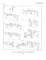
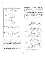
Страница 98: ...TM 11 6625 3071 14 3478A Figure 7 F 2 Simplified Schematic Of The Input Switching Circuitry 7 F 4 ...
Страница 111: ...TM 11 6625 3071 14 Figure 7 F 17 3478A Simplified Reference Circuitry 7 F 16 ...
Страница 122: ...TM 11 6625 3071 14 Table A 2 A 2 HP IB Worksheet A 4 ...
Страница 137: ...TM 11 6625 3071 14 Figure 7 D 2 Flow chart A 7 D 3 ...
Страница 139: ...TM 11 6625 3071 14 Figure 7 G 2 3478A Block Diagram 7 G 3 ...
Страница 140: ...TM 11 6625 3071 14 Component Locator for Input Circuitry and Ohms Current Source 7 G 4 ...
Страница 141: ...TM 11 6625 3071 14 Figure 7 G 3 Input Circuitry and Ohms Current Source 7 G 5 ...
Страница 142: ...TM 11 6625 3071 14 F G 6 ...
Страница 143: ...TM 11 6625 3071 14 2 Figure 7 G 4 AC to DC Converter 7 G 7 ...
Страница 144: ...TM 11 6625 3071 14 Component Locator for A D Converter and Control Logic 7 G 8 ...
Страница 145: ...TM 11 6625 3071 14 3 Figure 7 G 5 A D Converter and Control Logic 7 G 9 ...
Страница 146: ...TM 11 6625 3071 14 7 G 10 ...
Страница 147: ...TM 11 6625 3071 14 4 Figure 7 G 6 Power Supplies 7 G 11 7 G 12 blank ...
Страница 148: ......
Страница 149: ...PIN NO 057444 ...

