TM 11-6625-3071-14
3478A
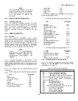
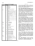
Table 3-4. Status Byte Definitions
Octal
Decimal
Bit
Definitions
Code
Code
001
1
0
Data Ready - Indicates to the controller
that measurement data is ready to be
output. The Require Service Message
and bit is cleared when the controller
begins to accept the data or when the
reading is no longer available. See
paragraph 114.
002
2
1
This bit is always at 0 (0=high).
004
4
2
Syntax Error - This shows that an
invalid Program Code(s) has been sent
to the 3478A (e.g. F9).
010
8
3
Internal Error - Shows that a failure in
the 3478A is detected. This may be a
failure in the Self-Test Routine (see
paragraph 3-60), the A/D Converter, or
a checksum error in the Calibration
RAM (checked every time a reading is
taken). More information can be
obtained by reading the 3478A’s error
register. See paragraph 3-120.
020
16
4
Front Panel SRQ - This bit is set when
the 3478A’s Front Panel SRQ button is
pressed. See paragraph 3-115.
040
32
5
Invalid Calibration - When this bit is
set, an attempt to calibrate the 3478A
has failed.
100
64
6
This is the SRQ bit. This bit is true
only if a Require Service Message is
output.
200
128
7
Power-On SRQ - Shows that a
power-on reset has occurred. See
paragraph 3-106.
Note: More than one bit in the Status Byte can be true
(see paragraph 3-87). is output (the Status Register’s
Data Ready bit is true). The only way the SRQ Message
is output is if the Front Panel SRQ condition is true.
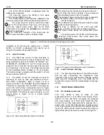
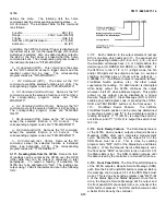
3-87. More than one bit in the Status Byte Message can
be true. For example, bit 0, 2, and 4 are true
(remember, bit 6 is true for any SRQ condition, if the
SRQ Mask is set for the condition) making the resultant
Status Byte look like the following:
NOTE
A "1" in this example shows a true condition.
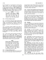
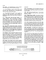
3-88. The byte is output as shown in the previous example
with the corresponding octal number of the example at 125
shown as follows:
3-89. Status Bit. The 3478A does not respond to a Parallel
Poll. The Status Bit is used only for Parallel Poll and should
not be confused with the bits in the Status Byte Message.
3-90. Pass Control. The 3478A does not have controller
capabilities.
3-91. Abort (Interface Clear). All HP-IB communication is
terminated (including the 3478A’s Bus communication).
Control is returned to the controller. The Abort Message does
not remove the 3478A from remote control.
3-92. 3478A Addressing
3-93. HP-IB requires that each device on the Bus needs to be
identified as a Listener or a Talker, in order to execute the
Bus Messages and commands. Because of this, each device
has its own unique "listen" and "talk" address. The address of
the 3478A is set by the Address Switch on its rear panel.
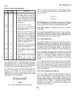
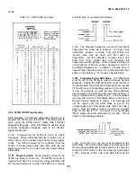
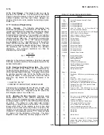
Setting the 3478A’s Listen Address also sets its Talk Address.
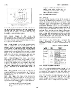
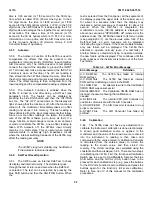
3-94. The address switch is an eight section "DIP" switch with
five sections used for addressing. The switch is shown in
Table 3-5. The allowable address settings are also listed in
Table 3-5. The factory address setting of the 3478A is
decimal 23 (refer to Section II of this manual for the switch
setting).
3-95. Instrument address commands (sent by the controller)
are usually in this form: universal unlisten, device talk, device
listen. The universal unlisten command removes all listeners
from the Bus to allow only the addressed listener(s) to receive
data. The data is sent by a talker which is designated by the
device talk command.
3-96. Talk- Only Mode (No Controller)
3-97. The 3478A’s Talk-Only Mode allows the multimeter to
send measurement data to an external device (like a printer)
without a Bus controller. The multimeter is placed into the
Talk-Only Mode by setting the five address switches (on the
rear panel "DIP" switch) to 1 (set only the five address
switches to the up position). Measurement data is then
output after each trigger. Function and range settings are
selected from the front panel.
3-10
Содержание 3478A
Страница 2: ...TM 11 6625 3071 14 A ...
Страница 4: ...TM 11 6625 3071 14 C D BLANK ...
Страница 12: ...TM 11 6625 3071 14 Table 1 1 Specification 1 2 ...
Страница 13: ...TM 11 6625 3071 14 Table 1 1 Specifications Cont 1 3 ...
Страница 14: ...TM 11 6625 3071 14 Table 1 1 Specifications Cont 1 4 ...
Страница 53: ...TM 11 6625 3071 14 1 ...
Страница 54: ...TM 11 6625 3071 14 2 ...
Страница 55: ...TM 11 6625 3071 14 3 ...
Страница 56: ...TM 11 6625 3071 14 4 ...
Страница 87: ...TM 11 6625 3071 14 3478A Figure 7 D 3 Flowchart B 7 D 5 ...
Страница 88: ...TM 11 6625 3071 14 3478A Figure 7 D 4 Flowchart C 7 D 6 ...
Страница 91: ...TM 11 6625 3071 14 3478A Figure 7 D 6 Flowchart D 7 D 9 ...
Страница 98: ...TM 11 6625 3071 14 3478A Figure 7 F 2 Simplified Schematic Of The Input Switching Circuitry 7 F 4 ...
Страница 111: ...TM 11 6625 3071 14 Figure 7 F 17 3478A Simplified Reference Circuitry 7 F 16 ...
Страница 122: ...TM 11 6625 3071 14 Table A 2 A 2 HP IB Worksheet A 4 ...
Страница 137: ...TM 11 6625 3071 14 Figure 7 D 2 Flow chart A 7 D 3 ...
Страница 139: ...TM 11 6625 3071 14 Figure 7 G 2 3478A Block Diagram 7 G 3 ...
Страница 140: ...TM 11 6625 3071 14 Component Locator for Input Circuitry and Ohms Current Source 7 G 4 ...
Страница 141: ...TM 11 6625 3071 14 Figure 7 G 3 Input Circuitry and Ohms Current Source 7 G 5 ...
Страница 142: ...TM 11 6625 3071 14 F G 6 ...
Страница 143: ...TM 11 6625 3071 14 2 Figure 7 G 4 AC to DC Converter 7 G 7 ...
Страница 144: ...TM 11 6625 3071 14 Component Locator for A D Converter and Control Logic 7 G 8 ...
Страница 145: ...TM 11 6625 3071 14 3 Figure 7 G 5 A D Converter and Control Logic 7 G 9 ...
Страница 146: ...TM 11 6625 3071 14 7 G 10 ...
Страница 147: ...TM 11 6625 3071 14 4 Figure 7 G 6 Power Supplies 7 G 11 7 G 12 blank ...
Страница 148: ......
Страница 149: ...PIN NO 057444 ...


