


TM 11-6625-3071-14
3478A
verter. All ac ranging is done in the AC to DC Con-
verter.
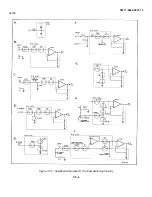
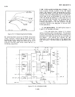
7-F-27. The AC to DC Converter consists of three
amplifier stages and a True RMS Converter. The pur-
pose of the amplifier stages is to provide the same full
scale input voltage to the RMS Converter for all full scale
ac inputs, and to be a buffer between the converter and
the ac inputs. The True RMS Converter does the actual
ac to dc conversion. The following explains the cir- cuitry
operation.
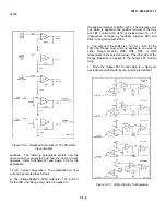
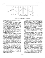
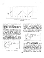
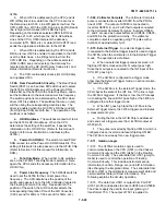
7-F-28. Amplifier Stages. Refer to Figure 7-F-5 and
Schematic 2 for the following explanation.
a.
The first amplifier stage (U301A) is an inverting
amplifier with gains of X.00, X. 1, or XI (dependent on
the ac range and function selected). The gains are
deter- mined by resistors RAI, RA2, RA3, and RAII (all in
U102), as shown in Figure 7-F-5. Capacitor C302 and
resistor R305 are used for high frequency compensation
(for flat gains at high frequency). The gain determining
resistors are selected by MOSFETS SIAC through
S6AC, and SIIAC (all in U102) which operate as
switches. The gains of the amplifier and FETs selected
for the ac functions are listed in Table 7-F-2.
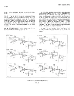
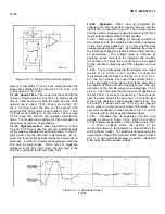
b.
The second amplifier stage (U301B) is an
inverting amplifier with gains of X.4 or X4 (dependent on
the ac
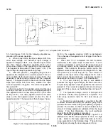
Figure 7-F-5. AC Gain Configurations
7-F-8
Содержание 3478A
Страница 2: ...TM 11 6625 3071 14 A ...
Страница 4: ...TM 11 6625 3071 14 C D BLANK ...
Страница 12: ...TM 11 6625 3071 14 Table 1 1 Specification 1 2 ...
Страница 13: ...TM 11 6625 3071 14 Table 1 1 Specifications Cont 1 3 ...
Страница 14: ...TM 11 6625 3071 14 Table 1 1 Specifications Cont 1 4 ...
Страница 53: ...TM 11 6625 3071 14 1 ...
Страница 54: ...TM 11 6625 3071 14 2 ...
Страница 55: ...TM 11 6625 3071 14 3 ...
Страница 56: ...TM 11 6625 3071 14 4 ...
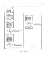
Страница 87: ...TM 11 6625 3071 14 3478A Figure 7 D 3 Flowchart B 7 D 5 ...
Страница 88: ...TM 11 6625 3071 14 3478A Figure 7 D 4 Flowchart C 7 D 6 ...
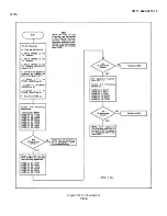
Страница 91: ...TM 11 6625 3071 14 3478A Figure 7 D 6 Flowchart D 7 D 9 ...
Страница 98: ...TM 11 6625 3071 14 3478A Figure 7 F 2 Simplified Schematic Of The Input Switching Circuitry 7 F 4 ...
Страница 111: ...TM 11 6625 3071 14 Figure 7 F 17 3478A Simplified Reference Circuitry 7 F 16 ...
Страница 122: ...TM 11 6625 3071 14 Table A 2 A 2 HP IB Worksheet A 4 ...
Страница 137: ...TM 11 6625 3071 14 Figure 7 D 2 Flow chart A 7 D 3 ...
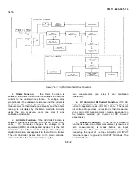
Страница 139: ...TM 11 6625 3071 14 Figure 7 G 2 3478A Block Diagram 7 G 3 ...
Страница 140: ...TM 11 6625 3071 14 Component Locator for Input Circuitry and Ohms Current Source 7 G 4 ...
Страница 141: ...TM 11 6625 3071 14 Figure 7 G 3 Input Circuitry and Ohms Current Source 7 G 5 ...
Страница 142: ...TM 11 6625 3071 14 F G 6 ...
Страница 143: ...TM 11 6625 3071 14 2 Figure 7 G 4 AC to DC Converter 7 G 7 ...
Страница 144: ...TM 11 6625 3071 14 Component Locator for A D Converter and Control Logic 7 G 8 ...
Страница 145: ...TM 11 6625 3071 14 3 Figure 7 G 5 A D Converter and Control Logic 7 G 9 ...
Страница 146: ...TM 11 6625 3071 14 7 G 10 ...
Страница 147: ...TM 11 6625 3071 14 4 Figure 7 G 6 Power Supplies 7 G 11 7 G 12 blank ...
Страница 148: ......
Страница 149: ...PIN NO 057444 ...


