Hardware configuration.
CNC 8070
5.
CENTRAL
UNIT + MONITO
R (ETX PLATFORM).
Ha
rd
ware function
ality.
Co
nne
ctors.
·72·
(R
EF
: 1911)
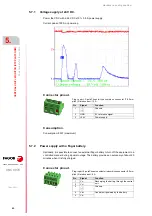
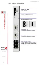
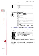
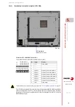
Power supply.
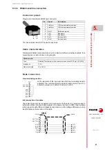
3-pin male Phoenix-contact combicom connector (7.62 mm pitch).
Connector to power the central unit with universal 24 V DC. See
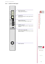
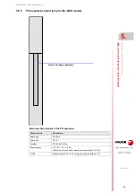
Protection fuse.
The module has a 5 A fuse that may be accessed from the outside to protect against over-
voltage (greater than 36 V DC or 25 V AC).
Auxiliary 24V output to supply the operator panel.
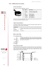
3-pin male Phoenix-contact minicombicon connector (3.5 mm pitch).
This connector offers the possibility to supply voltage from the central unit to the operator
panel. It is mainly oriented to those configurations where the operator panel is integrated into
the monitor (LCD-10K) or close to it.
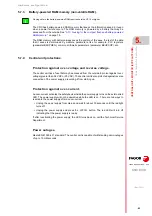
·BATTERY· connector . Battery voltage and charge.
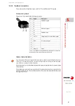
5-pin male Phoenix-contact minicombicon connector (3.5 mm pitch).
This connector can also be used to connect an external battery that ensures the proper shut-
down of the unit due to a power failure. The battery provides an autonomy of about 20 minutes
when it is fully charged.
·LATCH· button and status LED's.
When the red LED is on, it means that there is an over-current at the power supply and it
is not running. The ·LATCH· button may be used to reactivate the power supply after an over-
current.
3
2
1
+24 V
GND
Chassis
Signal.
Function.
Chassis
Shield.
GND
Power supply.
+24 V
Power supply.
3
2
1
+24 V
GND
Chassis
Signal.
Function.
Chassis
Shield.
GND
Power supply.
+24 V
Power supply.
5
4
3
2
1
Vbat -
Vbat +
Chassis
Vch +
Vch -
Signal
Function
Vbat -
Vbat +
Central unit powered by the battery.
Chassis
Shield.
Vch -
Vch +
Recharging the battery through the central unit.
Содержание CNC 8070
Страница 1: ...Ref 1911 8070 CNC Hardware configuration...
Страница 8: ...BLANK PAGE 8...
Страница 14: ...BLANK PAGE 14...
Страница 18: ...BLANK PAGE 18...
Страница 22: ...BLANK PAGE 22...
Страница 24: ...BLANK PAGE 24...
Страница 26: ...BLANK PAGE 26...
Страница 28: ...Hardware configuration CNC 8070 1 PREVIOUS INFORMATION 28 REF 1911...
Страница 38: ...Hardware configuration CNC 8070 2 CONFIGURATION General diagram for U60 Q7 A platform 38 REF 1911...
Страница 94: ...Hardware configuration CNC 8070 6 CENTRAL UNIT MONITOR Q7 A PLATFORM 94 REF 1911 C70 15AT...
Страница 184: ...Hardware configuration CNC 8070 8 LCD 15SVGA PASSIVE MONITOR LCD15 SVGA Overall connection 184 REF 1911...
Страница 272: ...Hardware configuration CNC 8070 18 INSTALLING A SENSOR FOR GAP CONTROL LASER MODEL 272 REF 1911...
Страница 273: ...Hardware configuration CNC 8070 273 User notes REF 1911...
Страница 274: ...Hardware configuration CNC 8070 274 User notes REF 1911...
Страница 275: ...Hardware configuration CNC 8070 275 User notes REF 1911...


