Hardware configuration.
CNC 8070
5.
CENTRAL
UNIT + MONITO
R (ETX PLATFORM).
Sp
ec
ific
at
io
ns
.
·50·
(R
EF
: 1911)
The machine manufacturer must comply with the EN 60204-1 (IEC-204-1) regulation
regarding electrical shocks in case of defective input/output pins with external power supply
when not plugging the connector before turning the power supply on.
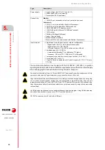
Power supply.
• Supply voltage: 24 V DC ±10 % and 3.5 A.
• Current peak of 90 A on power-up.
• Consumption: 85 W (maximum).
Connectivity.
Monitor.
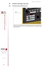
• 1 USB 2.0 port, accessible at the front, protected by a cover.
Central unit.
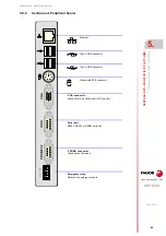
• 2 USB 1.1 ports (model with a Pentium M processor).
• 4 USB 2.0 ports (models with a T56N processor).
• 1 RS-232/422/485 (115 kbps) serial port.
• 1 LAN RJ45 port for Ethernet 10/100BaseT network.
• 1 VGA output.
• CAN Bus (CANfagor/CANopen).
• Sercos II bus (optional).
• Mechatrolink bus (optional).
• Mouse with PS-2 connector (model with Pentium M processor).
Inputs/outputs.
• 8 digital inputs and 8 digital inputs or outputs (configurable).
- Digital inputs. 24 V DC, 5 mA (typical consumption).
- Digital outputs: 24 V DC, 500 mA.
ON cycle: minimum 75 µs (25 µs, optional in two of them).
• 2 feedback inputs (5 V 0.250 A).
- Incremental differential TTL or differential TTL signal.
- Frequency : 100 kHz (TTL) / 1000 kHz (TTL differential).
• 1 emergency relay with two normally open contacts (1 A at 24 V).
• 2 probe inputs (5 V or 24 V)
• 1 input for three handwheels with A and B signals (5 V DC TTL) (only
C70-10K).
Type.
Description.
Do not get into the inside of the unit. This unit MUST NOT be opened by unauthorized personnel. Only
personnel authorized by Fagor Automation may access the interior of this unit.
Fagor Automation offers several flash compact in its catalog to increase storage space; if you are going
to use other compact flashes, always use industrial grade compact flash SLC; they support
temperatures between -40ºC and +80ºC (-40 ºF and 176 ºF) and last 27 years with 1000 writes per day.
Fagor Automation shall not be held responsible for any problems caused by using other lower-quality
compact flash.
No USB devices must be used nor connected while executing a part program. Using USB devices may
slow down the execution or cause some "RT-IT overflow" type error.
DO NOT connect any kind of hub to the USB port.
Содержание CNC 8070
Страница 1: ...Ref 1911 8070 CNC Hardware configuration...
Страница 8: ...BLANK PAGE 8...
Страница 14: ...BLANK PAGE 14...
Страница 18: ...BLANK PAGE 18...
Страница 22: ...BLANK PAGE 22...
Страница 24: ...BLANK PAGE 24...
Страница 26: ...BLANK PAGE 26...
Страница 28: ...Hardware configuration CNC 8070 1 PREVIOUS INFORMATION 28 REF 1911...
Страница 38: ...Hardware configuration CNC 8070 2 CONFIGURATION General diagram for U60 Q7 A platform 38 REF 1911...
Страница 94: ...Hardware configuration CNC 8070 6 CENTRAL UNIT MONITOR Q7 A PLATFORM 94 REF 1911 C70 15AT...
Страница 184: ...Hardware configuration CNC 8070 8 LCD 15SVGA PASSIVE MONITOR LCD15 SVGA Overall connection 184 REF 1911...
Страница 272: ...Hardware configuration CNC 8070 18 INSTALLING A SENSOR FOR GAP CONTROL LASER MODEL 272 REF 1911...
Страница 273: ...Hardware configuration CNC 8070 273 User notes REF 1911...
Страница 274: ...Hardware configuration CNC 8070 274 User notes REF 1911...
Страница 275: ...Hardware configuration CNC 8070 275 User notes REF 1911...

