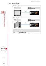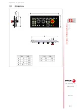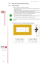
Hardware configuration.
CNC 8070
VERTICAL KEYB
/ VE
RTICAL
KEYB+MOUSE.
11.
Bus CAN
(CAN
fag
or/CANope
n protocols).
·227·
(R
EF
: 1911)
11.7.1
Identification of the modules at the bus.
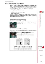
Each one of the elements integrated into the CAN bus is identified by its address or node
number. The CNC must always occupy position "0" and the rest of the elements of the bus
will occupy consecutive positions starting with "1". The node address or number also sets
the priority of the group within the bus; the lower the number the higher the priority. We
recommend to set the priority of the groups as follows (from highest to lowest).
• The groups that have the feedback inputs.
• The groups that have analog inputs and outputs.
• The groups that have digital inputs and outputs.
• The keyboard and jog panel.
In order for any change in the identification of the module to take effect, the CNC must be
restarted and turn off/on the corresponding module; however, we recommend to change the
address while the modules and the CNC are off.
Configuring the address (node number).
Address (node) of the element within the bus (0-15).
Address (node) of the element within the bus (16-31).
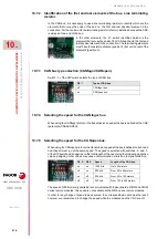
Switch ·4· of the DIP switch selects the positions or elements integrated in the CAN bus may
be expanded up to 32.
Each one of the elements integrated into the CAN bus is identified
by the 16-position rotary switch (0-15) "Address" (also referred to
as "Node_Select").
DS ·4·
Address (node) of the element.
off
Positions 0-15 within the bus.
on
Positions 16-31 within the bus.
ADDRESS
0
1
2
3
···
13
14
15
DS4 = 0
0
1
2
3
···
13
14
15
DS4 = 1
16
17
18
19
···
29
30
31
4
0F
E
D
C
B
A
9
8
7 6 5 3 2
1
ID4 = 0
ADDRESS = 2
ADDRESS = 18
ON
ID3
ID2
ID1
4
0F
E
D
C
B
A
9
8
7 6 5 3 2
1
ADDRESS = 2
ID4 = 1
ON
ID3
ID2
ID1
ADDRESS = 2
Содержание CNC 8070
Страница 1: ...Ref 1911 8070 CNC Hardware configuration...
Страница 8: ...BLANK PAGE 8...
Страница 14: ...BLANK PAGE 14...
Страница 18: ...BLANK PAGE 18...
Страница 22: ...BLANK PAGE 22...
Страница 24: ...BLANK PAGE 24...
Страница 26: ...BLANK PAGE 26...
Страница 28: ...Hardware configuration CNC 8070 1 PREVIOUS INFORMATION 28 REF 1911...
Страница 38: ...Hardware configuration CNC 8070 2 CONFIGURATION General diagram for U60 Q7 A platform 38 REF 1911...
Страница 94: ...Hardware configuration CNC 8070 6 CENTRAL UNIT MONITOR Q7 A PLATFORM 94 REF 1911 C70 15AT...
Страница 184: ...Hardware configuration CNC 8070 8 LCD 15SVGA PASSIVE MONITOR LCD15 SVGA Overall connection 184 REF 1911...
Страница 272: ...Hardware configuration CNC 8070 18 INSTALLING A SENSOR FOR GAP CONTROL LASER MODEL 272 REF 1911...
Страница 273: ...Hardware configuration CNC 8070 273 User notes REF 1911...
Страница 274: ...Hardware configuration CNC 8070 274 User notes REF 1911...
Страница 275: ...Hardware configuration CNC 8070 275 User notes REF 1911...


