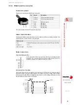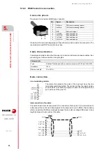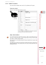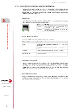
Hardware configuration.
CNC 8070
5.
CENTRAL
UNIT + MONITO
R (ETX PLATFORM).
Conn
ecti
ons.
·90·
(R
EF
: 1911)
Cable handling.
Fagor supplies the cable with the terminals protected by a cap. Remove the protection cap
before connecting the cable.
Module identification.
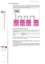
The drives are identified with the 16-bit rotary switch "Address" (also called "Node_Select").
This switch selects the address (node) occupied by each of the elements integrated into the
Sercos connection. The CNC does not have the switch; this CNC is pre-configured to always
occupy position ·0· at the bus.
The CNC must always occupy position 0 and the drives will occupy consecutive positions
starting with 1. In order for any change at the "Address" switch to be assumed, the
corresponding drive must be reset and the CNC powered off and back on.
The fact that the drive identified with number 1 (for example) corresponds to the X axis, to
Y or to another one is irrelevant. However, it is a good idea, for clarity sake, that the machine
axes X, Y, Z, U, V, W, A, B and C be assigned consecutive numbers in that order.
SFO-V-FLEX cable.
Flexibility.
Minimum static bending radius of 45 mm and a dynamic radius of 60 mm.
Cover.
PUR. Polyurethane resistant to chemical used on machines.
Temperature.
Work: -40 ºC / 80 ºC (-40 ºF / 176 ºF).
Storage: -40 ºC / 80 ºC (-40 ºF / 176 ºF).
To remove the terminal protecting cap or to connect or
disconnect the cable, hold the cable by its terminal; never
pull the cable by holding its plastic part because it could
render it useless.
Then set certain CNC machine parameters to configure the connection.
i
Содержание CNC 8070
Страница 1: ...Ref 1911 8070 CNC Hardware configuration...
Страница 8: ...BLANK PAGE 8...
Страница 14: ...BLANK PAGE 14...
Страница 18: ...BLANK PAGE 18...
Страница 22: ...BLANK PAGE 22...
Страница 24: ...BLANK PAGE 24...
Страница 26: ...BLANK PAGE 26...
Страница 28: ...Hardware configuration CNC 8070 1 PREVIOUS INFORMATION 28 REF 1911...
Страница 38: ...Hardware configuration CNC 8070 2 CONFIGURATION General diagram for U60 Q7 A platform 38 REF 1911...
Страница 94: ...Hardware configuration CNC 8070 6 CENTRAL UNIT MONITOR Q7 A PLATFORM 94 REF 1911 C70 15AT...
Страница 184: ...Hardware configuration CNC 8070 8 LCD 15SVGA PASSIVE MONITOR LCD15 SVGA Overall connection 184 REF 1911...
Страница 272: ...Hardware configuration CNC 8070 18 INSTALLING A SENSOR FOR GAP CONTROL LASER MODEL 272 REF 1911...
Страница 273: ...Hardware configuration CNC 8070 273 User notes REF 1911...
Страница 274: ...Hardware configuration CNC 8070 274 User notes REF 1911...
Страница 275: ...Hardware configuration CNC 8070 275 User notes REF 1911...


