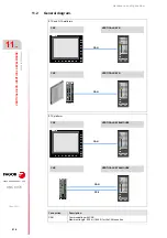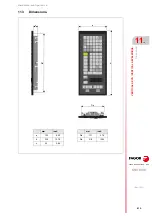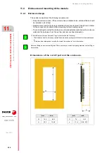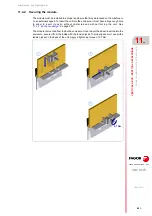
Hardware configuration.
CNC 8070
VERTICAL KEYB
/ VE
RTICAL
KEYB+MOUSE.
11.
Hardw
are fu
ncti
ona
lities.
·223·
(R
EF
: 1911)
11.6
Hardware functionalities.
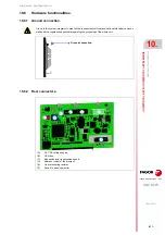
11.6.1
Ground connection.
11.6.2
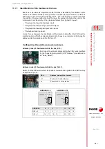
Rear connectors.
It is up to the system integrator to meet all the requirements of local and national electrical codes as
well as all the regulations applicable regarding the grounding of the whole unit.
(A)
24 V DC voltage supply.
(B)
CAN bus.
(C)
Bus switch and transmission speed.
(D)
Address (node) of the element.
(E)
Line terminating resistor.
(F)
Keys of a passive monitor.
Ground connection.
A
B
C
D
E
F
B
Содержание CNC 8070
Страница 1: ...Ref 1911 8070 CNC Hardware configuration...
Страница 8: ...BLANK PAGE 8...
Страница 14: ...BLANK PAGE 14...
Страница 18: ...BLANK PAGE 18...
Страница 22: ...BLANK PAGE 22...
Страница 24: ...BLANK PAGE 24...
Страница 26: ...BLANK PAGE 26...
Страница 28: ...Hardware configuration CNC 8070 1 PREVIOUS INFORMATION 28 REF 1911...
Страница 38: ...Hardware configuration CNC 8070 2 CONFIGURATION General diagram for U60 Q7 A platform 38 REF 1911...
Страница 94: ...Hardware configuration CNC 8070 6 CENTRAL UNIT MONITOR Q7 A PLATFORM 94 REF 1911 C70 15AT...
Страница 184: ...Hardware configuration CNC 8070 8 LCD 15SVGA PASSIVE MONITOR LCD15 SVGA Overall connection 184 REF 1911...
Страница 272: ...Hardware configuration CNC 8070 18 INSTALLING A SENSOR FOR GAP CONTROL LASER MODEL 272 REF 1911...
Страница 273: ...Hardware configuration CNC 8070 273 User notes REF 1911...
Страница 274: ...Hardware configuration CNC 8070 274 User notes REF 1911...
Страница 275: ...Hardware configuration CNC 8070 275 User notes REF 1911...


