Hardware configuration.
CNC 8070
7.
CENTRAL U
N
IT
FOR C
ABI
NET (Q7-A
PLATFORM).
Ha
rdware
function
ali
ty
(conne
ctors).
·148·
(R
EF
: 1911)
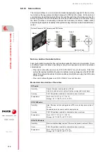
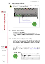
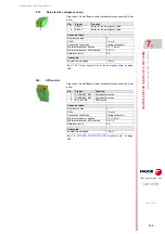
7.6.4
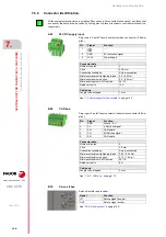
Connector identification.
·A22·
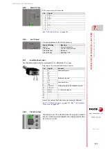
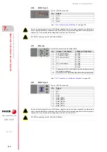
24 V DC supply input.
·B28· CAN
bus.
·B32· Sercos
II
bus.
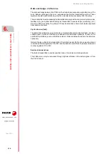
All the equipment connectors are polarized (they can only be connected in one sense) and those that
are exactly the same are also coded by coding pins to prevent incorrect or accidental connection,
respectively.
i
Connector data.
Number of poles.
3.
Pitch.
5.08 mm.
Connection technique.
Screw connection.
Minimum/maximum tightening torque. 0.5 / 0.6 Nm.
Minimum/maximum section.
0.2 / 2.5 mm².
Minimum/maximum AWG section.
24 / 12.
Rated current In.
12 A.
Cable data.
Length to be stripped.
7 mm.
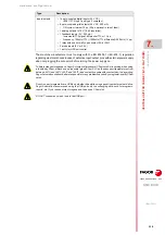
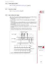
"7.4 Power supply for the module."
Connector data.
Number of poles.
5.
Pitch.
3.5 mm.
Connection technique.
Screw connection.
Minimum/maximum tightening torque. 0.22 / 0.25 Nm.
Minimum/maximum section.
0.14 / 1.5 mm².
Minimum/maximum AWG section.
28 / 16.
Rated current In.
8 A.
Cable data.
Length to be stripped.
7 mm.
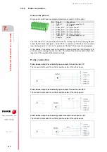
Plug-in part. 3-pole Phoenix-contact combicon connector (5.08 mm
pitch).
Pin
Signal.
Function.
1
- - -.
2
GND
0 V reference signal.
3
+24 V
Power supply.
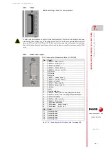
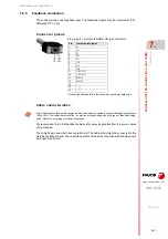
Plug-in part. 5-pole Phoenix-contact minicombicon connector (3.5 mm
pitch).
Pin.
Signal.
Function.
1
GND
Ground / 0 V.
2
CL
(LOW) bus signal.
3
SH
CAN shield.
4
CH
(HIGH) bus signal.
5
SH
CAN shield.
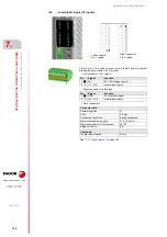
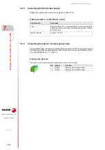
Sercos-II emitter and receiver.
Signal.
Function.
IN
Sercos signal receiver.
OUT
Sercos signal emitter.
Содержание CNC 8070
Страница 1: ...Ref 1911 8070 CNC Hardware configuration...
Страница 8: ...BLANK PAGE 8...
Страница 14: ...BLANK PAGE 14...
Страница 18: ...BLANK PAGE 18...
Страница 22: ...BLANK PAGE 22...
Страница 24: ...BLANK PAGE 24...
Страница 26: ...BLANK PAGE 26...
Страница 28: ...Hardware configuration CNC 8070 1 PREVIOUS INFORMATION 28 REF 1911...
Страница 38: ...Hardware configuration CNC 8070 2 CONFIGURATION General diagram for U60 Q7 A platform 38 REF 1911...
Страница 94: ...Hardware configuration CNC 8070 6 CENTRAL UNIT MONITOR Q7 A PLATFORM 94 REF 1911 C70 15AT...
Страница 184: ...Hardware configuration CNC 8070 8 LCD 15SVGA PASSIVE MONITOR LCD15 SVGA Overall connection 184 REF 1911...
Страница 272: ...Hardware configuration CNC 8070 18 INSTALLING A SENSOR FOR GAP CONTROL LASER MODEL 272 REF 1911...
Страница 273: ...Hardware configuration CNC 8070 273 User notes REF 1911...
Страница 274: ...Hardware configuration CNC 8070 274 User notes REF 1911...
Страница 275: ...Hardware configuration CNC 8070 275 User notes REF 1911...

