Hardware configuration.
CNC 8070
CENTR
A
L UNIT (CPU) ENCLOSURE (Q7-A
PLATFORM).
4.
·43·
(R
EF
: 1911)
4
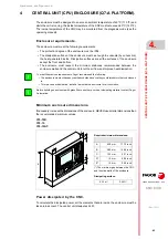
CENTRAL UNIT (CPU) ENCLOSURE (Q7-A PLATFORM).
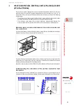
The enclosure must be designed to ensure an ambient temperature of 45 ºC (113 ºF) and
while the unit is running, the inside temperature of the CNC must not exceed 60 ºC (140 ºF).
The inside temperature of the CNC may be monitored from the diagnosis mode (see the
operating manual).
Enclosure requirements.
The enclosure must meet the following requirements.
• The protection degree of the enclosure must be IP54.
• The dissipation surface of the enclosure must be enough to evacuate (by convection)
the heat generated inside. Dissipation surfaces are all the surfaces of the enclosure
except the front and bottom.
• The enclosure must respect the minimum distances recommended between the
enclosure walls and the central unit to let the air flow and improve heat dissipation.
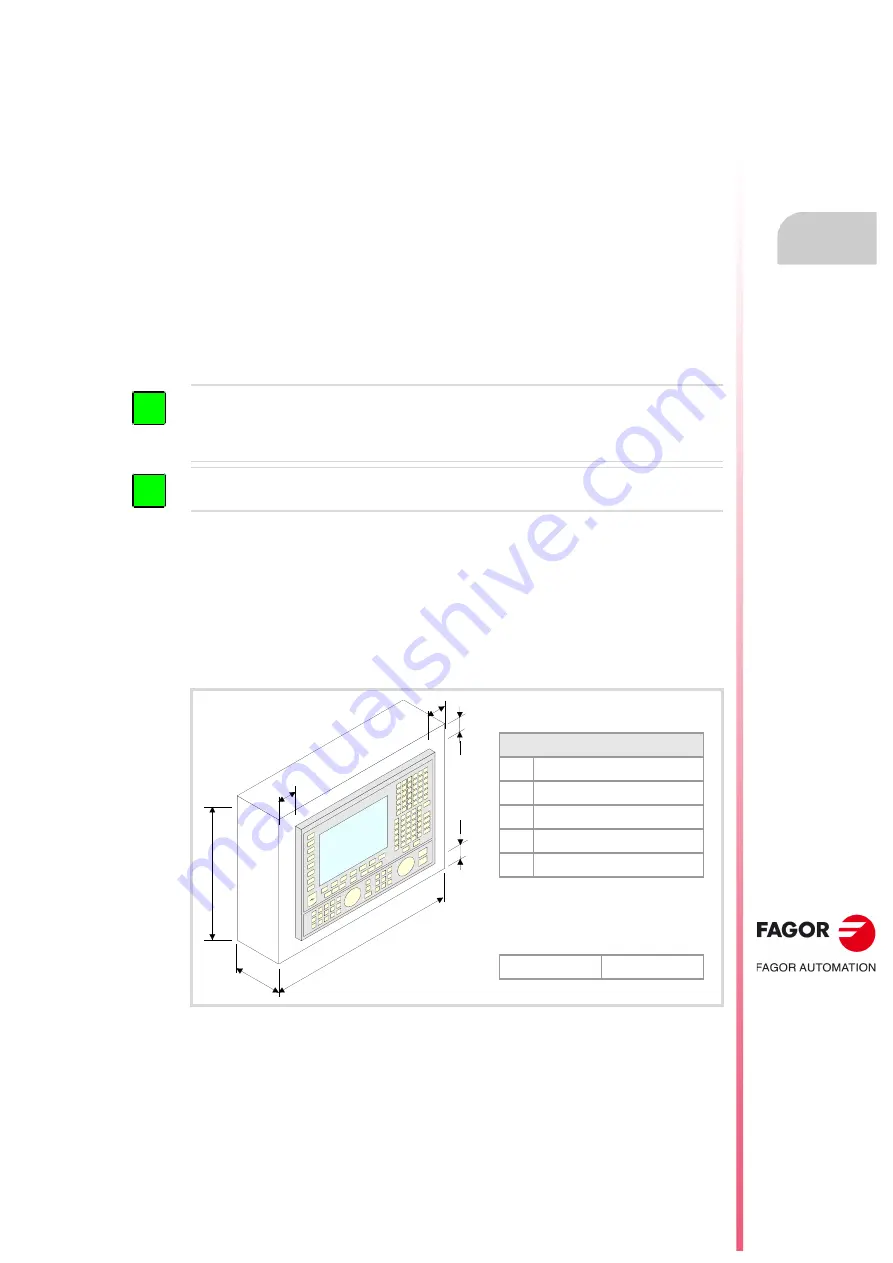
Minimum enclosure dimensions.
If necessary, increase the dimensions of the enclosure; NEVER use smaller dimensions than
the recommended minimum values.
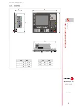
C70-10K.
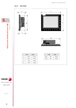
C70-15.
C70-15AT.
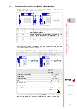
Power dissipated by the CNC.
To calculate the dissipated power, all the elements that are inside the enclosure must be
taken into account. The central unit dissipates 24 W.
To meet the previous requirements, Fagor recommends the following.
• The enclosure must not have any ventilation holes, because they could let dust or other substances
in.
• To improve heat dissipation, install a fan inside the enclosure for air circulation.
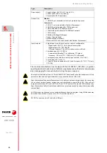
Before building an enclosure with glass fiber u another poor heat dissipating material, contact Fagor
Automation.
i
i
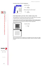
Required minimum dimensions:
(*) The minimum gap between the CNC
and the side walls of the enclosure.
Dissipating surface:
A
450 mm
17,72 inch
B
380 mm
14,96 inch
C
135 mm
5.31 inch
D*
15 mm
0.59 inch
E*
15 mm
0.59 inch
0.33 m²
3.55 ft²
A
B
C
E
E
D
D
Содержание CNC 8070
Страница 1: ...Ref 1911 8070 CNC Hardware configuration...
Страница 8: ...BLANK PAGE 8...
Страница 14: ...BLANK PAGE 14...
Страница 18: ...BLANK PAGE 18...
Страница 22: ...BLANK PAGE 22...
Страница 24: ...BLANK PAGE 24...
Страница 26: ...BLANK PAGE 26...
Страница 28: ...Hardware configuration CNC 8070 1 PREVIOUS INFORMATION 28 REF 1911...
Страница 38: ...Hardware configuration CNC 8070 2 CONFIGURATION General diagram for U60 Q7 A platform 38 REF 1911...
Страница 94: ...Hardware configuration CNC 8070 6 CENTRAL UNIT MONITOR Q7 A PLATFORM 94 REF 1911 C70 15AT...
Страница 184: ...Hardware configuration CNC 8070 8 LCD 15SVGA PASSIVE MONITOR LCD15 SVGA Overall connection 184 REF 1911...
Страница 272: ...Hardware configuration CNC 8070 18 INSTALLING A SENSOR FOR GAP CONTROL LASER MODEL 272 REF 1911...
Страница 273: ...Hardware configuration CNC 8070 273 User notes REF 1911...
Страница 274: ...Hardware configuration CNC 8070 274 User notes REF 1911...
Страница 275: ...Hardware configuration CNC 8070 275 User notes REF 1911...


