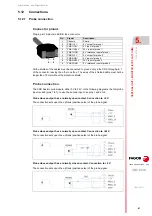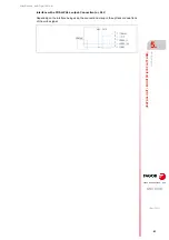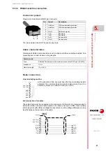
Hardware configuration.
CNC 8070
CENTRAL
UNIT + MONITO
R (ETX PLATFORM).
5.
In
sert the boa
rd into th
e PC
I expa
nsion
(on
ly in MCU
mo
dels).
·79·
(R
EF
: 1911)
5.11
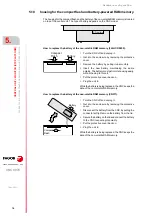
Insert the board into the PCI expansion (only in MCU models).
Precaution when handling the boards.
Handle the boards very carefully to avoid damaging them or their elements, contacts or
conducting lines. Place the modules in the correct position. Do not use a sharp-pointed object
(like a screwdriver) as a lever.
• Before handling the ESD boards, discharge their static electricity (for example by
touching an object that is connected to ground).
• The units and tools being used must be free of any static charge-
• Turn the power supply of the unit off before inserting or removing the board.
• Hold the ESD board only at its corners or edges; do not touch its components, contacts
or conducting lines.
Voltage for the pins V(I/O).
The supply voltage for the V(I/O) pins of the connector may be set for 5V or 3.3V (by default,
5 V). See
"5.8.5 PCI expansion board (only for the MCU model)."
Mounting the boards.
This symbol identifies the cards as ESD components (sensitive to electrostatic
discharges). Bear in mind the following considerations when handing boards with
ESD:
Do not open the unit or handle the internal boards while the unit is connected to power. Before opening
the unit, make sure that the unit is unplugged from the power outlet.
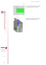
Remove the three mounting screws (A) of the lid,
located on top and slide the lid in the direction of the
arrow (B).
Loosen the locking angle bracket (C) and turn it to allow
the board to slide in. Insert the board in the slot (D) and
push it in the direction of the arrow (E) all the way in.
A
A
A
B
C
D
E
Содержание CNC 8070
Страница 1: ...Ref 1911 8070 CNC Hardware configuration...
Страница 8: ...BLANK PAGE 8...
Страница 14: ...BLANK PAGE 14...
Страница 18: ...BLANK PAGE 18...
Страница 22: ...BLANK PAGE 22...
Страница 24: ...BLANK PAGE 24...
Страница 26: ...BLANK PAGE 26...
Страница 28: ...Hardware configuration CNC 8070 1 PREVIOUS INFORMATION 28 REF 1911...
Страница 38: ...Hardware configuration CNC 8070 2 CONFIGURATION General diagram for U60 Q7 A platform 38 REF 1911...
Страница 94: ...Hardware configuration CNC 8070 6 CENTRAL UNIT MONITOR Q7 A PLATFORM 94 REF 1911 C70 15AT...
Страница 184: ...Hardware configuration CNC 8070 8 LCD 15SVGA PASSIVE MONITOR LCD15 SVGA Overall connection 184 REF 1911...
Страница 272: ...Hardware configuration CNC 8070 18 INSTALLING A SENSOR FOR GAP CONTROL LASER MODEL 272 REF 1911...
Страница 273: ...Hardware configuration CNC 8070 273 User notes REF 1911...
Страница 274: ...Hardware configuration CNC 8070 274 User notes REF 1911...
Страница 275: ...Hardware configuration CNC 8070 275 User notes REF 1911...

