Hardware configuration.
CNC 8070
CENTRAL U
N
IT
FOR C
ABI
NET (Q7-A
PLATFORM).
7.
Conn
ecti
ons.
·163·
(R
EF
: 1911)
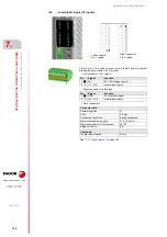
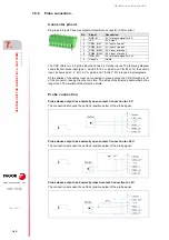
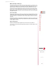
Probe whose output has a normally closed contact. Connection to +24 V.
The connection acts upon the up flank (positive pulse) of the probe signal.
Interface with an open-collector output. Connection to +5 V.
The connection acts upon the down flank (negative pulse) of the probe signal.
Interface with an open-collector output. Connection to +24 V.
The connection acts upon the down flank (negative pulse) of the probe signal.
Interface with a PUSH-PULL output. Connection to +5 V.
Depending on the interface being used, the connection acts upon the up flank or down flank
of the probe signal.
Содержание CNC 8070
Страница 1: ...Ref 1911 8070 CNC Hardware configuration...
Страница 8: ...BLANK PAGE 8...
Страница 14: ...BLANK PAGE 14...
Страница 18: ...BLANK PAGE 18...
Страница 22: ...BLANK PAGE 22...
Страница 24: ...BLANK PAGE 24...
Страница 26: ...BLANK PAGE 26...
Страница 28: ...Hardware configuration CNC 8070 1 PREVIOUS INFORMATION 28 REF 1911...
Страница 38: ...Hardware configuration CNC 8070 2 CONFIGURATION General diagram for U60 Q7 A platform 38 REF 1911...
Страница 94: ...Hardware configuration CNC 8070 6 CENTRAL UNIT MONITOR Q7 A PLATFORM 94 REF 1911 C70 15AT...
Страница 184: ...Hardware configuration CNC 8070 8 LCD 15SVGA PASSIVE MONITOR LCD15 SVGA Overall connection 184 REF 1911...
Страница 272: ...Hardware configuration CNC 8070 18 INSTALLING A SENSOR FOR GAP CONTROL LASER MODEL 272 REF 1911...
Страница 273: ...Hardware configuration CNC 8070 273 User notes REF 1911...
Страница 274: ...Hardware configuration CNC 8070 274 User notes REF 1911...
Страница 275: ...Hardware configuration CNC 8070 275 User notes REF 1911...

