Hardware configuration.
CNC 8070
CENTRAL U
N
IT
FOR C
ABI
NET (Q7-A
PLATFORM).
7.
Conn
ecti
ons.
·159·
(R
EF
: 1911)
7.8
Connections.
7.8.1
Ground connection.
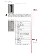
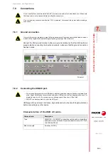
Connect the CNC ground terminal to the main ground terminal so that the EMC performs
properly. Before connecting the inputs and outputs, make sure that the ground connection
has been made.
7.8.2
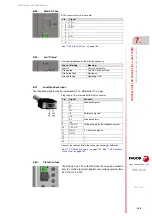
Connecting the USB2.0 port.
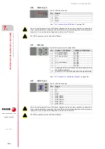
USB support for pen drives, hard drives, keyboards and mice; check with Fagor Automation
before connecting any other device.
Characteristics of the USB 2.0 cable.
Do not handle the connectors while the CNC is turned on (inputs/outputs, feedback, etc.). Make sure
that the device is not powered before handling the connectors.
Do not make any connections while the CNC is powered. Disconnect the power before making a
connection.
It is up to the system integrator to meet all the requirements of local and national electrical codes as
well as all the regulations applicable regarding the grounding of the whole unit.
• Do not run part programs from a USB device, whether it be when using a pendrive or external hard
drive. Fagor Automation recommends using the USB port only to exchanging data, such for
programs, reports, etc. If you require more storage space, then use a CFast disk.
• DO NOT connect any kind of hub to the USB port.
Ground.
Characteristic.
Description.
Type.
28AWG/1P + 24AWG/2C construction cables with dual shielding
and ferrite cores on both ends. Recommended reference; CNC Tech
102-1030-BL-F0500.
Maximum length.
5 meters (16.40 ft).
Содержание CNC 8070
Страница 1: ...Ref 1911 8070 CNC Hardware configuration...
Страница 8: ...BLANK PAGE 8...
Страница 14: ...BLANK PAGE 14...
Страница 18: ...BLANK PAGE 18...
Страница 22: ...BLANK PAGE 22...
Страница 24: ...BLANK PAGE 24...
Страница 26: ...BLANK PAGE 26...
Страница 28: ...Hardware configuration CNC 8070 1 PREVIOUS INFORMATION 28 REF 1911...
Страница 38: ...Hardware configuration CNC 8070 2 CONFIGURATION General diagram for U60 Q7 A platform 38 REF 1911...
Страница 94: ...Hardware configuration CNC 8070 6 CENTRAL UNIT MONITOR Q7 A PLATFORM 94 REF 1911 C70 15AT...
Страница 184: ...Hardware configuration CNC 8070 8 LCD 15SVGA PASSIVE MONITOR LCD15 SVGA Overall connection 184 REF 1911...
Страница 272: ...Hardware configuration CNC 8070 18 INSTALLING A SENSOR FOR GAP CONTROL LASER MODEL 272 REF 1911...
Страница 273: ...Hardware configuration CNC 8070 273 User notes REF 1911...
Страница 274: ...Hardware configuration CNC 8070 274 User notes REF 1911...
Страница 275: ...Hardware configuration CNC 8070 275 User notes REF 1911...

