Hardware configuration.
CNC 8070
CEN
T
RAL UNIT + MONITOR (Q7-A
PLATFORM).
6.
Conn
ecti
ons.
·131·
(R
EF
: 1911)
6.8.11
CAN bus.
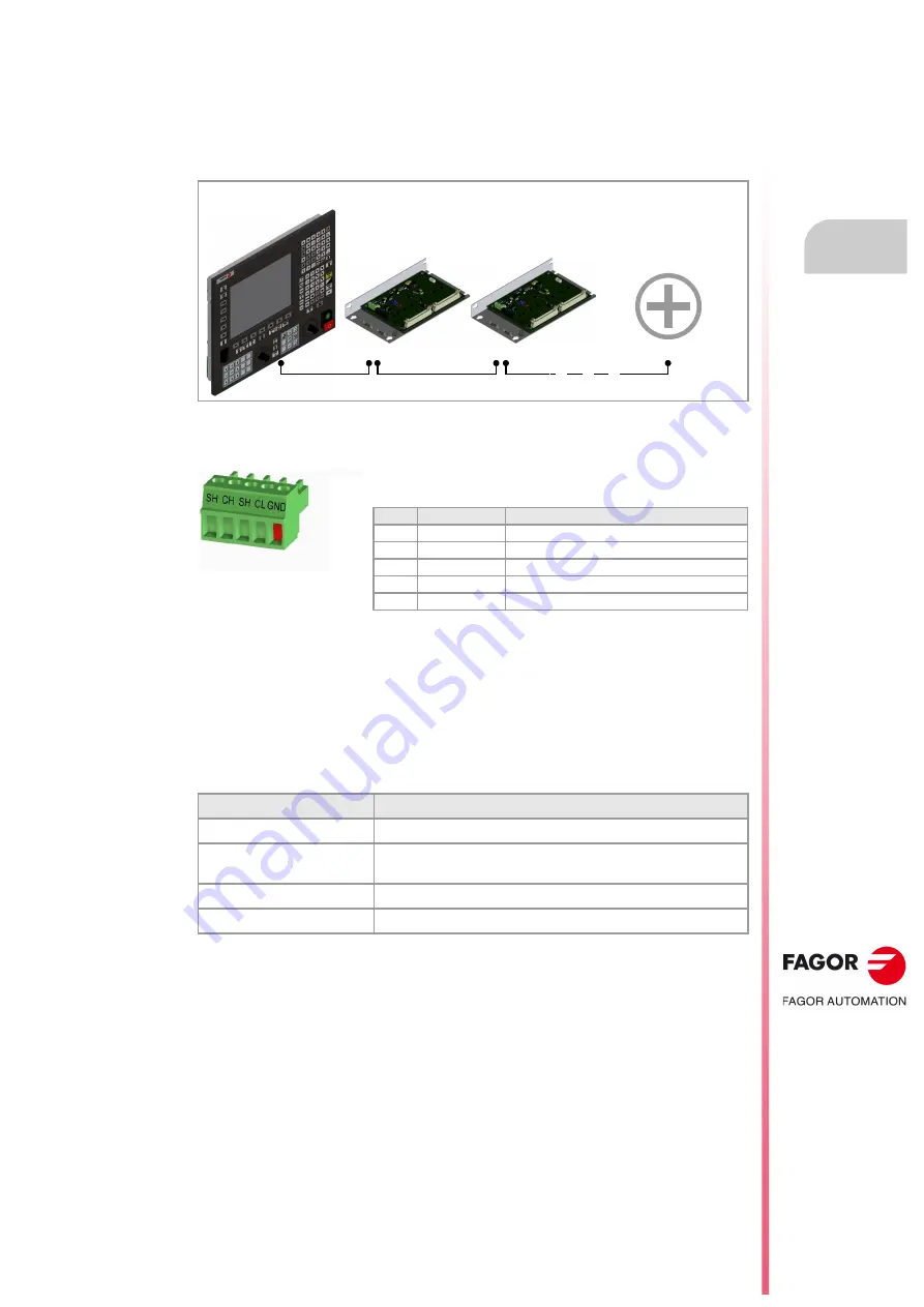
CANopen is a network communication protocol based on the CAN bus system for connecting
the CNC with remote modules and keyboards. The CAN connection supports up to 32
devices (nodes), including the central unit; more one than keyboard and several groups of
remote modules are possible.
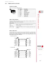
CAN connector.
The cable shield must be connected to the connector at both ends. The connector has two
shield pins. Both pins are equivalent; the CAN shield may be connected to either one.
Characteristics of the CAN cable.
Use a specific CAN cable. The ends of all the wires and the shield must be protected by the
corresponding terminal (pin). Also use the terminals (pins) to secure the cable to the
connector.
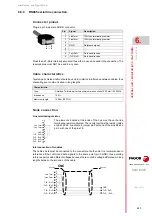
CAN bus with CNC (master) and RIOR modules.
Characteristic.
Description.
Type.
Shielded. Twisted pair (1 x 2 x 0.22 mm²).
Flexibility.
Extremely flexible. Minimum bending radius, static = 50 mm and
dynamic = 95 mm.
Cover.
PUR
Impedance.
Cat.5 (100
- 120
)
Master
Node 1
Node 2
CAN bus.
B28
B28A
B28B
B28A
B28B
Node n
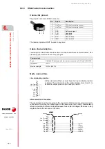
Plug-in part. 5-pole Phoenix-contact minicombicon connector (3.5 mm
pitch).
Pin.
Signal.
Function.
1
GND
Ground / 0 V.
2
CL
(LOW) bus signal.
3
SH
CAN shield.
4
CH
(HIGH) bus signal.
5
SH
CAN shield.
Содержание CNC 8070
Страница 1: ...Ref 1911 8070 CNC Hardware configuration...
Страница 8: ...BLANK PAGE 8...
Страница 14: ...BLANK PAGE 14...
Страница 18: ...BLANK PAGE 18...
Страница 22: ...BLANK PAGE 22...
Страница 24: ...BLANK PAGE 24...
Страница 26: ...BLANK PAGE 26...
Страница 28: ...Hardware configuration CNC 8070 1 PREVIOUS INFORMATION 28 REF 1911...
Страница 38: ...Hardware configuration CNC 8070 2 CONFIGURATION General diagram for U60 Q7 A platform 38 REF 1911...
Страница 94: ...Hardware configuration CNC 8070 6 CENTRAL UNIT MONITOR Q7 A PLATFORM 94 REF 1911 C70 15AT...
Страница 184: ...Hardware configuration CNC 8070 8 LCD 15SVGA PASSIVE MONITOR LCD15 SVGA Overall connection 184 REF 1911...
Страница 272: ...Hardware configuration CNC 8070 18 INSTALLING A SENSOR FOR GAP CONTROL LASER MODEL 272 REF 1911...
Страница 273: ...Hardware configuration CNC 8070 273 User notes REF 1911...
Страница 274: ...Hardware configuration CNC 8070 274 User notes REF 1911...
Страница 275: ...Hardware configuration CNC 8070 275 User notes REF 1911...


