Hardware configuration.
CNC 8070
9.
MONITOR-21 MULTITOUCH.
Co
nne
ctors.
·194·
(R
EF
: 1911)
9.7
Connectors.
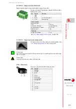
·T/S RS232· Touch screen driver (not recommended).
·T/S USB· Touch screen driver (recommended).
Option recommended by Fagor Automation for the touch controller.
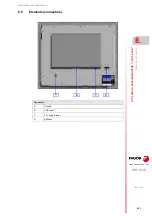
Bottom view.
(1) T/S RS-232Touch screen driver (consult Fagor Automation).
(2) T/S USBTouch screen driver (recommended).
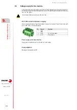
(3) 24 V DC IN24 V DC supply input (recommended).
(4) 12 V DC IN12 V DC supply input (consult Fagor Automation).
(5) DVI-DDVI-D video signal input.
(6) VGAVGA video signal input.
(7) Ground connection.
Ground connection.
A
B
C
D
E
F
G
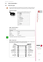
Plug-in part 9-pin female SUB-D HD connector.
Pin.
Signal.
Function.
1
DCD
Data Carrier Detect.
2
RxD
Received Data.
3
TxD
Transmit Data.
4
DTR
Data Terminal Ready.
5
GND Ground.
6
DSR
Data Set Ready.
7
RTS
Request To Send.
8
CTS
Clear To Send.
9
RI
Ring Indicator.
1 ... 5
6 ... 9
Touch controller.
Fagor Automation recommends using the USB driver for the touch screen. Consult Fagor Automation
before using the RS232 driver.
i
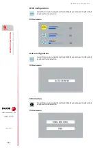
USB type-B controller. Plug-in part.
Maximum length; 5 m (16.40 feet).
Pin.
Signal.
1
+ 5 V DC.
2
Data -.
3
Data +.
4
GND.
1
2
4
3
Using cables with a length longer than 5 m or extension cords can cause problems in terms of
compliance with EMC directives; before using this type of cables in an industrial setting, check whether
the installation complies with regulations.
i
Содержание CNC 8070
Страница 1: ...Ref 1911 8070 CNC Hardware configuration...
Страница 8: ...BLANK PAGE 8...
Страница 14: ...BLANK PAGE 14...
Страница 18: ...BLANK PAGE 18...
Страница 22: ...BLANK PAGE 22...
Страница 24: ...BLANK PAGE 24...
Страница 26: ...BLANK PAGE 26...
Страница 28: ...Hardware configuration CNC 8070 1 PREVIOUS INFORMATION 28 REF 1911...
Страница 38: ...Hardware configuration CNC 8070 2 CONFIGURATION General diagram for U60 Q7 A platform 38 REF 1911...
Страница 94: ...Hardware configuration CNC 8070 6 CENTRAL UNIT MONITOR Q7 A PLATFORM 94 REF 1911 C70 15AT...
Страница 184: ...Hardware configuration CNC 8070 8 LCD 15SVGA PASSIVE MONITOR LCD15 SVGA Overall connection 184 REF 1911...
Страница 272: ...Hardware configuration CNC 8070 18 INSTALLING A SENSOR FOR GAP CONTROL LASER MODEL 272 REF 1911...
Страница 273: ...Hardware configuration CNC 8070 273 User notes REF 1911...
Страница 274: ...Hardware configuration CNC 8070 274 User notes REF 1911...
Страница 275: ...Hardware configuration CNC 8070 275 User notes REF 1911...

