Hardware configuration.
CNC 8070
6.
CEN
T
RAL UNIT + MONITOR (Q7-A
PLATFORM).
Enclosu
re
a
nd securin
g of
the modu
les.
·100·
(R
EF
: 1911)
6.3
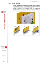
Enclosure and securing of the modules.
6.3.1
Ambient characteristics of the enclosure.
The enclosure must be designed to ensure an ambient temperature of 45 ºC (113 ºF) and
while the unit is running, the inside temperature of the CNC must not exceed 60 ºC (140 ºF).
The inside temperature of the CNC may be monitored from the diagnosis mode (see the
operating manual).
6.3.2
Enclosure design.
The enclosure must meet the following requirements:
• The enclosure must have enough surface area to evacuate by convection the heat
generated inside.
• The enclosure must respect the minimum distances recommended between the
enclosure walls and the central unit to let the air flow and improve heat dissipation.
• In the connector area, reserve a space that allows the cables to be connected, respecting
their radius of curvature. Special care must be taken with the Sercos connection because
bending the optic fiber too much could break it
• Keep the enclosure clean.
To meet the previous requirements, Fagor recommends the following.
• The enclosure must have an air input next to the cables and an air output next to the fan.
In this case, install fans to ventilate the enclosure and keep the temperature within the
allowed limits. Bear in mind that this air flow through the unit extracts hot air to the outside,
but it allows dirt into the enclosure. Fagor recommends installing anti-dust filters at the
air inputs and outputs.
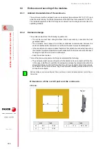
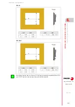
Dimensions of the cut off part and the enclosure.
C70-10K.
Before building an enclosure with glass fiber u another poor heat dissipating material, contact Fagor
Automation.
i
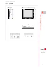
mm
inch
W
391
15.40
H
321
12.63
mm
inch
e
1.5 - 4
0.06 - 0.16
H
W
e
Содержание CNC 8070
Страница 1: ...Ref 1911 8070 CNC Hardware configuration...
Страница 8: ...BLANK PAGE 8...
Страница 14: ...BLANK PAGE 14...
Страница 18: ...BLANK PAGE 18...
Страница 22: ...BLANK PAGE 22...
Страница 24: ...BLANK PAGE 24...
Страница 26: ...BLANK PAGE 26...
Страница 28: ...Hardware configuration CNC 8070 1 PREVIOUS INFORMATION 28 REF 1911...
Страница 38: ...Hardware configuration CNC 8070 2 CONFIGURATION General diagram for U60 Q7 A platform 38 REF 1911...
Страница 94: ...Hardware configuration CNC 8070 6 CENTRAL UNIT MONITOR Q7 A PLATFORM 94 REF 1911 C70 15AT...
Страница 184: ...Hardware configuration CNC 8070 8 LCD 15SVGA PASSIVE MONITOR LCD15 SVGA Overall connection 184 REF 1911...
Страница 272: ...Hardware configuration CNC 8070 18 INSTALLING A SENSOR FOR GAP CONTROL LASER MODEL 272 REF 1911...
Страница 273: ...Hardware configuration CNC 8070 273 User notes REF 1911...
Страница 274: ...Hardware configuration CNC 8070 274 User notes REF 1911...
Страница 275: ...Hardware configuration CNC 8070 275 User notes REF 1911...

