Hardware configuration.
CNC 8070
CENTRAL
UNIT + MONITO
R (ETX PLATFORM).
5.
Powe
r sup
ply fo
r the modu
le.
·63·
(R
EF
: 1911)
5.7.3
Battery-powered RAM memory (non-volatile RAM).
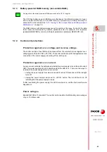
The CNC has battery-powered RAM memory that keeps the information saved in it even
when a power failure occurs. The RAM memory is powered by a battery that may be
accessed from the outside. See
"5.10 housing for the compact flash and battery-powered
The RAM memory with battery always saves the position of the axes, the rest of the data
that it saves is determined by machine parameters, like for example, PLC registers
(parameter BKUPREG), common arithmetic parameters (parameter BKUPCUP), etc.
5.7.4
Central unit protections.
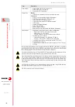
Protection against over-voltage and reverse voltage.
The central unit has a fuse that may be accessed from the outside to protect against over-
voltage (greater than 36 V DC or 25 V AC). The central unit is also protected against reverse
connection of the power supply, preventing it from starting up.
Protection against over-current.
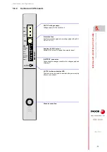
An over-current activates the safety device inside the power supply turns on the external red
LED. The power supply will not be operative while the LED is on. There are two ways to
reactivate the power supply after an over-current.
• Unplug the power supply from mains and wait for about 30 seconds until the red light
turns off.
• Unplug the power supply and press the ·LATCH· button. The red LED will turn off
indicating that the power supply is ready.
If after reactivating the power supply, the LED turns back on, call the Technical Service
Department.
Power outages.
Meets EN 61000-4-11 standard. The central unit is capable of withstanding micro-outages
of up to 10 milliseconds.
Saving data in the battery-powered RAM required version V3.14 or higher.
i
Содержание CNC 8070
Страница 1: ...Ref 1911 8070 CNC Hardware configuration...
Страница 8: ...BLANK PAGE 8...
Страница 14: ...BLANK PAGE 14...
Страница 18: ...BLANK PAGE 18...
Страница 22: ...BLANK PAGE 22...
Страница 24: ...BLANK PAGE 24...
Страница 26: ...BLANK PAGE 26...
Страница 28: ...Hardware configuration CNC 8070 1 PREVIOUS INFORMATION 28 REF 1911...
Страница 38: ...Hardware configuration CNC 8070 2 CONFIGURATION General diagram for U60 Q7 A platform 38 REF 1911...
Страница 94: ...Hardware configuration CNC 8070 6 CENTRAL UNIT MONITOR Q7 A PLATFORM 94 REF 1911 C70 15AT...
Страница 184: ...Hardware configuration CNC 8070 8 LCD 15SVGA PASSIVE MONITOR LCD15 SVGA Overall connection 184 REF 1911...
Страница 272: ...Hardware configuration CNC 8070 18 INSTALLING A SENSOR FOR GAP CONTROL LASER MODEL 272 REF 1911...
Страница 273: ...Hardware configuration CNC 8070 273 User notes REF 1911...
Страница 274: ...Hardware configuration CNC 8070 274 User notes REF 1911...
Страница 275: ...Hardware configuration CNC 8070 275 User notes REF 1911...


