Hardware configuration.
CNC 8070
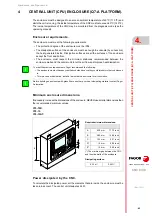
CENTR
A
L UNIT (CPU) ENCLOSURE (Q7-A
PLATFORM).
4.
Calcu
lation
o
f th
e surfa
ce need
ed for
h
eat dissipa
tion.
·45·
(R
EF
: 1911)
4.1
Calculation of the surface needed for heat dissipation.
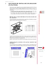
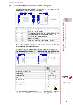
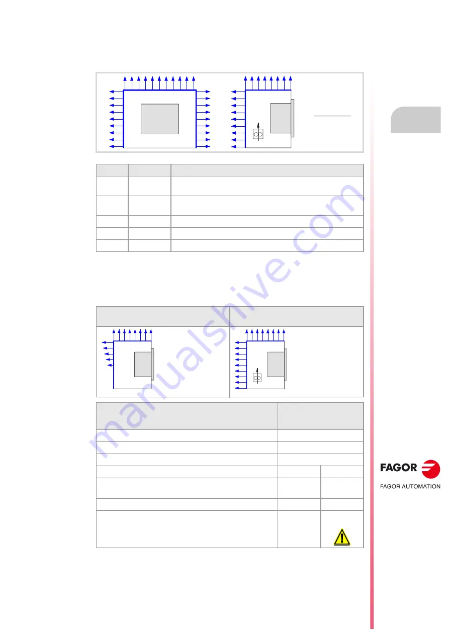
To calculate the total surface required for the enclosure, in order to dissipate the heat
generated in it, the following data must be considered.
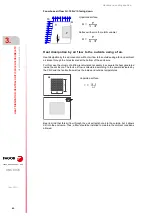
H e a t d i s s i p a t i o n e x a m p l e f o r a n e n c l o s u r e w i t h t h e
recommended minimum surface.
The dissipation coefficient corresponds to an enclosure made of painted sheet metal.
In this case, for an inside temperature of 45 ºC (113 ºF), the enclosure must be larger or an
inside fan must be installed to improve heat dissipation by making the air flow inside.
Data
Units
Meaning
TO
(m²)
Total required surface (The entire surface of the enclosure except the
bottom one is considered useful).
P
(W)
Total power dissipated by all the elements that generate heat inside the
enclosure, including the power supply and the fan, if there is one.
Ta
(ºC)
Ambient temperature (outside the enclosure).
Ts
(ºC)
Internal CNC temperature.
Cf
(m²)
Dissipation coefficient of the material used for the enclosure.
Heat dissipation by natural convection.
Heat dissipation by forced convection with
internal fan (flow Q = 13.6 m³/h).
C70-10K
C70-15.
C70-15AT
Ambient (room) temperature (Ta).
45 ºC (113 ºF)
Dissipated power.
24 W
Dissipating surface.
0.33 m² (3.,55 ft²)
Fan.
Yes
No
Air flow of the fan.
13.6
m³/h
- - -
Dissipation coefficient.
6.2
4.2
Internal CNC temperature.
56.5 ºC
133.7 ºF
62.1 ºC
143.8 ºF
Ts
A
P
Ta
A =
P
Cf · (Ts-Ta)
Ts
Ta
A
P
A
P
4,2
Ts Ta
–
------------------------------
=
Ts
Ta
A
P
A
P
6,2
Ts Ta
–
------------------------------
=
Содержание CNC 8070
Страница 1: ...Ref 1911 8070 CNC Hardware configuration...
Страница 8: ...BLANK PAGE 8...
Страница 14: ...BLANK PAGE 14...
Страница 18: ...BLANK PAGE 18...
Страница 22: ...BLANK PAGE 22...
Страница 24: ...BLANK PAGE 24...
Страница 26: ...BLANK PAGE 26...
Страница 28: ...Hardware configuration CNC 8070 1 PREVIOUS INFORMATION 28 REF 1911...
Страница 38: ...Hardware configuration CNC 8070 2 CONFIGURATION General diagram for U60 Q7 A platform 38 REF 1911...
Страница 94: ...Hardware configuration CNC 8070 6 CENTRAL UNIT MONITOR Q7 A PLATFORM 94 REF 1911 C70 15AT...
Страница 184: ...Hardware configuration CNC 8070 8 LCD 15SVGA PASSIVE MONITOR LCD15 SVGA Overall connection 184 REF 1911...
Страница 272: ...Hardware configuration CNC 8070 18 INSTALLING A SENSOR FOR GAP CONTROL LASER MODEL 272 REF 1911...
Страница 273: ...Hardware configuration CNC 8070 273 User notes REF 1911...
Страница 274: ...Hardware configuration CNC 8070 274 User notes REF 1911...
Страница 275: ...Hardware configuration CNC 8070 275 User notes REF 1911...


