Hardware configuration.
CNC 8070
·20·
(R
EF
: 1911)
PRECAUTIONS AGAINST DAMAGE TO THE PRODUCT
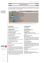
SAFETY SYMBOLS
Symbols that may appear in the manual.
Work environment.
This unit is ready to be used in industrial environments complying with
the directives and regulations effective in the European Community.
Fagor Automation shall not be held responsible for any damage
suffered or caused by the CNC when installed in other environments
(residential, homes, etc.).
Install this unit in the proper place.
It is recommended, whenever possible, to install the CNC away from
coolants, chemical product, blows, etc. that could damage it.
This unit meets the European directives on electromagnetic
compatibility. Nevertheless, it is recommended to keep it away from
sources of electromagnetic disturbance such as:
Powerful loads connected to the same mains as the unit.
Nearby portable transmitters (radio-telephones, Ham radio
transmitters).
Nearby radio / TC transmitters.
Nearby arc welding machines.
Nearby high voltage lines.
Enclosures.
It is up to the manufacturer to guarantee that the enclosure where the
unit has been installed meets all the relevant directives of the
European Union.
Avoid disturbances coming from the
machine.
The machine must have all the interference generating elements
(relay coils, contactors, motors, etc.) uncoupled.
Use the proper power supply.
Use an external regulated 24 Vdc power supply for the keyboard,
operator panel and the remote modules.
Connecting the power supply to ground.
The zero Volt point of the external power supply must be connected
to the main ground point of the machine.
Analog inputs and outputs connection.
Use shielded cables connecting all their meshes to the corresponding
pin.
Ambient conditions.
Maintain the CNC within the recommended temperature range, both
when running and not running. See the corresponding chapter in the
hardware manual.
Central unit enclosure.
To maintain the right ambient conditions in the enclosure of the central
unit, it must meet the requirements indicated by Fagor. See the
corresponding chapter in the hardware manual.
Power switch.
This switch must be easy to access and at a distance between 0.7 and
1.7 m (2.3 and 5.6 ft) off the floor.
Danger or prohibition symbol.
This symbol indicates actions or operations that may hurt people or damage products.
Warning or caution symbol.
This symbol indicates situations that certain operations could cause and the suggested actions to prevent
them.
Obligation symbol.
This symbol indicates actions and operations that must be carried out.
Information symbol.
This symbol indicates notes, warnings and advises.
Symbol for additional documentation.
This symbol indicates that there is another document with more detailed and specific information.
i
Содержание CNC 8070
Страница 1: ...Ref 1911 8070 CNC Hardware configuration...
Страница 8: ...BLANK PAGE 8...
Страница 14: ...BLANK PAGE 14...
Страница 18: ...BLANK PAGE 18...
Страница 22: ...BLANK PAGE 22...
Страница 24: ...BLANK PAGE 24...
Страница 26: ...BLANK PAGE 26...
Страница 28: ...Hardware configuration CNC 8070 1 PREVIOUS INFORMATION 28 REF 1911...
Страница 38: ...Hardware configuration CNC 8070 2 CONFIGURATION General diagram for U60 Q7 A platform 38 REF 1911...
Страница 94: ...Hardware configuration CNC 8070 6 CENTRAL UNIT MONITOR Q7 A PLATFORM 94 REF 1911 C70 15AT...
Страница 184: ...Hardware configuration CNC 8070 8 LCD 15SVGA PASSIVE MONITOR LCD15 SVGA Overall connection 184 REF 1911...
Страница 272: ...Hardware configuration CNC 8070 18 INSTALLING A SENSOR FOR GAP CONTROL LASER MODEL 272 REF 1911...
Страница 273: ...Hardware configuration CNC 8070 273 User notes REF 1911...
Страница 274: ...Hardware configuration CNC 8070 274 User notes REF 1911...
Страница 275: ...Hardware configuration CNC 8070 275 User notes REF 1911...

