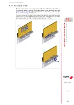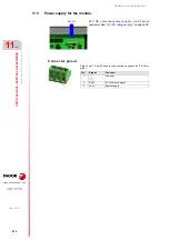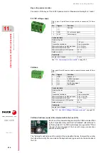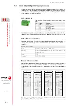
Hardware configuration.
CNC 8070
12.
HORIZONTAL
KEYB 2
.0
+ TOU
CHPAD.
Gen
eral di
agram.
·230·
(R
EF
: 1911)
12.2
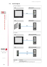
General diagram.
• Do not replace the cable supplied by Fagor.
• Do not connect any type of extension cord to the USB power cable.
• Connect the keyboard directly to the central unit; do not connect the keyboard to any type of hub.
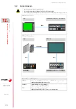
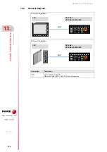
ETX and Q7-A platforms.
ETX and Q7-A platforms.
CNC
HORIZONTAL KEYB 2.0 + TOUCHPAD.
USB
CNC
PPC-21W
USB
HORIZONTAL KEYB 2.0 + TOUCHPAD.
CAN
ETHERNET
JOG-PANEL
Connection.
Description.
USB 2.0
Connection of a USB keyboard to the panel-PC. Use the keyboard cable.
Maximum cable length: 800 mm (2.62 ft).
Ethernet.
Connecting the CNC to the panel-PC.
Maximum cable length: 100 m (328 ft).
CAN
Connection of the operator panels.
Maximum length of bus; 500 m (1640 ft) for CANopen bus.
Содержание CNC 8070
Страница 1: ...Ref 1911 8070 CNC Hardware configuration...
Страница 8: ...BLANK PAGE 8...
Страница 14: ...BLANK PAGE 14...
Страница 18: ...BLANK PAGE 18...
Страница 22: ...BLANK PAGE 22...
Страница 24: ...BLANK PAGE 24...
Страница 26: ...BLANK PAGE 26...
Страница 28: ...Hardware configuration CNC 8070 1 PREVIOUS INFORMATION 28 REF 1911...
Страница 38: ...Hardware configuration CNC 8070 2 CONFIGURATION General diagram for U60 Q7 A platform 38 REF 1911...
Страница 94: ...Hardware configuration CNC 8070 6 CENTRAL UNIT MONITOR Q7 A PLATFORM 94 REF 1911 C70 15AT...
Страница 184: ...Hardware configuration CNC 8070 8 LCD 15SVGA PASSIVE MONITOR LCD15 SVGA Overall connection 184 REF 1911...
Страница 272: ...Hardware configuration CNC 8070 18 INSTALLING A SENSOR FOR GAP CONTROL LASER MODEL 272 REF 1911...
Страница 273: ...Hardware configuration CNC 8070 273 User notes REF 1911...
Страница 274: ...Hardware configuration CNC 8070 274 User notes REF 1911...
Страница 275: ...Hardware configuration CNC 8070 275 User notes REF 1911...

