Hardware configuration.
CNC 8070
INSTALLING AND CONFIGURING
A THIN CLIENT
(EPATEC
17.
·263·
(R
EF
: 1911)
17
INSTALLING AND CONFIGURING A THIN CLIENT
(EPATEC MODEL).
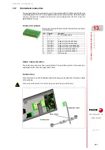
The Thin Client is recommended for configurations where the VGA cable cannot be used
to connect the central unit with a second monitor (e.g. the passive screen LCD-15SVGA)
due to too much distance. The central unit and the Thin Client will communicate via Ethernet
(local network or point to point) and the Thin Client will be in charge of sending the VGA signal
to the passive screen. Both monitors show the same video signal. A mouse connected to
the Thin Client may also be used with to interact with the CNC.
The central unit and the Thin Client communicate through a remote desktop software, in this
case VNC, where the CNC is the server and the Think Client is the client.
The passive screen permits having a second work station consisting of the screen itself and
an operator panel OP-PANEL-H/E. Connect the operator panel to the CAN bus of the system
and the softkeys of the screen to the operator panel.
The softkeys of the passive screen will only operative if they are connected to the horizontal or vertical
keyboard.
i
Point-to-point connection.
Connection within a local network (LAN).
VGA
CAN
ETHERNET
CAN
SOFTKEYS
LCD-15"
CPU
Q
W
E
R
T
Y
U
I
O
P
S
D
F
G
H
J
K
L
Ñ
A
Z
X
C
V
B
N
M
ALTGR
ALT
CTRL
CAPS
INS
DEL
MAIN
MENU
END
HOME
7
8
9
4
5
6
1
2
3
_
0
.
+
*
=
/
CUSTOM
RECALL
ENTER
,
.
-
{
}
^
ESC
SHIFT
SHIFT
<
SPACE
UTILITIES
TOOLS
TABLES
EDIT
MANUAL
AUTO
MDI
ETHERNET
LAN
ETHERNET
VGA
CAN
CAN
SOFTKEYS
LCD-15"
CPU
Q
W
E
R
T
Y
U
I
O
P
S
D
F
G
H
J
K
L
Ñ
A
Z
X
C
V
B
N
M
ALTGR
ALT
CTRL
CAPS
INS
DEL
MAIN
MENU
END
HOME
7
8
9
4
5
6
1
2
3
_
0
.
+
*
=
/
CUSTOM
RECALL
ENTER
,
.
-
{
}
^
ESC
SHIFT
SHIFT
<
SPACE
UTILITIES
TOOLS
TABLES
EDIT
MANUAL
AUTO
MDI
Содержание CNC 8070
Страница 1: ...Ref 1911 8070 CNC Hardware configuration...
Страница 8: ...BLANK PAGE 8...
Страница 14: ...BLANK PAGE 14...
Страница 18: ...BLANK PAGE 18...
Страница 22: ...BLANK PAGE 22...
Страница 24: ...BLANK PAGE 24...
Страница 26: ...BLANK PAGE 26...
Страница 28: ...Hardware configuration CNC 8070 1 PREVIOUS INFORMATION 28 REF 1911...
Страница 38: ...Hardware configuration CNC 8070 2 CONFIGURATION General diagram for U60 Q7 A platform 38 REF 1911...
Страница 94: ...Hardware configuration CNC 8070 6 CENTRAL UNIT MONITOR Q7 A PLATFORM 94 REF 1911 C70 15AT...
Страница 184: ...Hardware configuration CNC 8070 8 LCD 15SVGA PASSIVE MONITOR LCD15 SVGA Overall connection 184 REF 1911...
Страница 272: ...Hardware configuration CNC 8070 18 INSTALLING A SENSOR FOR GAP CONTROL LASER MODEL 272 REF 1911...
Страница 273: ...Hardware configuration CNC 8070 273 User notes REF 1911...
Страница 274: ...Hardware configuration CNC 8070 274 User notes REF 1911...
Страница 275: ...Hardware configuration CNC 8070 275 User notes REF 1911...

