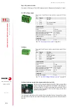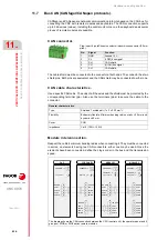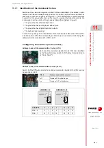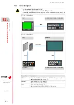
Hardware configuration.
CNC 8070
10.
HORIZONTAL KEYB
/ HO
RIZONTAL KEYB+MOUSE.
Bus CAN
(CAN
fag
or/CANope
n protocols).
·216·
(R
EF
: 1911)
10.7.2 Identification of the first and last elements of the bus. Line terminating
resistor.
In the CAN bus, it is necessary to use a line terminating resistor to identify which are the
elements that occupy the ends of the bus; i.e. the first and last physical element in the
connection. For the central unit, the terminating resistor is factory installed because the CNC
is always at one end of the bus.
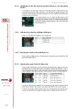
10.7.3 CAN bus type selection (CANfagor/CANopen).
Switch ·1· of the DIP switch selects the type of CAN bus.
10.7.4 Selecting the speed for the CANfagor bus.
When using the CANfagor protocol, the transmission speed at the bus is defined at the CNC
(parameter CANLENGTH).
10.7.5 Selecting the speed for the CANopen bus.
When using the CANopen protocol, the transmission speed at the bus is defined in each node
and they all must run at the same speed. The speed is selected with switches ·2· and ·3·
of the DIP switch and it depends on the total length of the bus. Using the following illustrative
values; assigning other values may cause communication errors due to signal distortion.
The speed of 250 kHz is only available to communicate with the keyboards, RIOW and RIOW
series remote modules; this speed is not available at the RIO5 series remote modules.
In order for any change of speed to be assumed, the corresponding module must be reset;
however, we recommend to change the speed while the modules and the CNC are off.
In the other elements, the ·LT· switch identifies which are the
elements that occupy the ends of the CAN bus; that is, the first and
last physical element in the connection. The terminating elements
must have the resistor activated (position 1) but not the rest of the
elements (position 0).
DS ·1·
Type of CAN bus.
off
CANfagor bus.
on
CANopen bus.
DS ·2· DS·3·
Speed
Length of the CAN bus.
on
on
1000 kHz
Up to 20 meters.
off
on
800 kHz
From 20 to 40 meters.
on
off
500 kHz
From 40 to 100 meters.
off
off
250 kHz
From 100 to 500 meters.
Содержание CNC 8070
Страница 1: ...Ref 1911 8070 CNC Hardware configuration...
Страница 8: ...BLANK PAGE 8...
Страница 14: ...BLANK PAGE 14...
Страница 18: ...BLANK PAGE 18...
Страница 22: ...BLANK PAGE 22...
Страница 24: ...BLANK PAGE 24...
Страница 26: ...BLANK PAGE 26...
Страница 28: ...Hardware configuration CNC 8070 1 PREVIOUS INFORMATION 28 REF 1911...
Страница 38: ...Hardware configuration CNC 8070 2 CONFIGURATION General diagram for U60 Q7 A platform 38 REF 1911...
Страница 94: ...Hardware configuration CNC 8070 6 CENTRAL UNIT MONITOR Q7 A PLATFORM 94 REF 1911 C70 15AT...
Страница 184: ...Hardware configuration CNC 8070 8 LCD 15SVGA PASSIVE MONITOR LCD15 SVGA Overall connection 184 REF 1911...
Страница 272: ...Hardware configuration CNC 8070 18 INSTALLING A SENSOR FOR GAP CONTROL LASER MODEL 272 REF 1911...
Страница 273: ...Hardware configuration CNC 8070 273 User notes REF 1911...
Страница 274: ...Hardware configuration CNC 8070 274 User notes REF 1911...
Страница 275: ...Hardware configuration CNC 8070 275 User notes REF 1911...

