Hardware configuration.
CNC 8070
CENTRAL U
N
IT
FOR C
ABI
NET (Q7-A
PLATFORM).
7.
Sp
ec
ific
at
io
ns
.
·139·
(R
EF
: 1911)
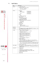
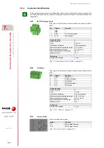
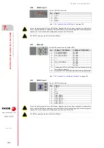
The machine manufacturer must comply with the EN 60204-1 (IEC-204-1) regulation
regarding electrical shocks in case of defective input/output pins with external power supply
when not plugging the connector before turning the power supply on.
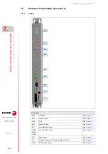
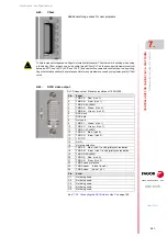
Inputs/outputs.
• 16 opto-coupled digital inputs (24 V DC).
- IEC61131-2 type 1 and type 3 compliant.
• 8 opto-coupled digital outputs (24 V DC, 500 mA).
- ON cycle: minimum 75 µs (25 µs, optional in two of them).
• 1 analog outputs (±10 V, 16-bit resolution).
• 1 feedback inputs (5 V, 250 mA).
- Incremental TTL signal, differential TTL or 1 Vpp.
- Frequency: 100 kHz (TTL) / 1000 kHz (TTL differential) / 500 kHz (1 Vpp).
• 1 relay with one normally open contact (1A at 24V).
• 2 probe inputs (5 V or 24 V)
• 1 entry for UPS unit control.
Type.
Description.
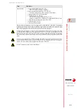
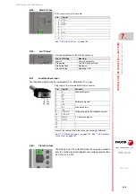
To help increase storage space, Fagor Automation lists several CFast cards in its catalog; when using
a third-party CFast, always use an industrial grade CFast SLC as these support temperatures from
between -40ºC and +85ºC (-40 ºF and 185 ºF) and can last five years with constant day-to-day writing.
Fagor Automation shall not be held responsible for any problems caused by using lower-quality CFast
cards.
Do not run part programs from a USB port, whether it be while using a pendrive or external hard drive.
Fagor Automation recommends using the USB port only to exchanging data, such for programs,
reports, etc. If you require more storage space, then use a CFast disk.
DO NOT connect any kind of hub to the USB port.
Содержание CNC 8070
Страница 1: ...Ref 1911 8070 CNC Hardware configuration...
Страница 8: ...BLANK PAGE 8...
Страница 14: ...BLANK PAGE 14...
Страница 18: ...BLANK PAGE 18...
Страница 22: ...BLANK PAGE 22...
Страница 24: ...BLANK PAGE 24...
Страница 26: ...BLANK PAGE 26...
Страница 28: ...Hardware configuration CNC 8070 1 PREVIOUS INFORMATION 28 REF 1911...
Страница 38: ...Hardware configuration CNC 8070 2 CONFIGURATION General diagram for U60 Q7 A platform 38 REF 1911...
Страница 94: ...Hardware configuration CNC 8070 6 CENTRAL UNIT MONITOR Q7 A PLATFORM 94 REF 1911 C70 15AT...
Страница 184: ...Hardware configuration CNC 8070 8 LCD 15SVGA PASSIVE MONITOR LCD15 SVGA Overall connection 184 REF 1911...
Страница 272: ...Hardware configuration CNC 8070 18 INSTALLING A SENSOR FOR GAP CONTROL LASER MODEL 272 REF 1911...
Страница 273: ...Hardware configuration CNC 8070 273 User notes REF 1911...
Страница 274: ...Hardware configuration CNC 8070 274 User notes REF 1911...
Страница 275: ...Hardware configuration CNC 8070 275 User notes REF 1911...

