Hardware configuration.
CNC 8070
CEN
T
RAL UNIT + MONITOR (Q7-A
PLATFORM).
6.
Ha
rdware
function
ali
ty
(conne
ctors).
·109·
(R
EF
: 1911)
·B64· EtherCAT
bus.
·E21·
Local feedback input.
Incremental feedback signals (TTL, differential TTL, Vpp).
·E36·
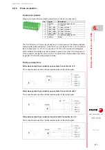
Handwheel input (only for C70-10K).
The LCD-10K model admits the connection of up to 3 handwheels (MPG1, MPG2 and
MPG3) with A and B signals (5 V DC TTL). If he handwheel has an axis selector button, the
button signal may be connected to a digital input and may be managed from the PLC using
the -NEXTMPGAXIS-mark.
RJ45 connector for 4-wire cable.
Pin.
Signal.
1
TD +
2
TD -
3
RD +
4
- - -
5
- - -
6
RD -
7
- - -
8
- - -
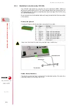
Plug-in part. 15-pin female SUB-D HD connector.
Connect the cable shield to the connector housing at both ends.
Pin.
Signal.
Function.
1
A
Feedback signals.
2
/A
3
B
4
/B
5
I0
Reference signals.
6
/I0
7
AL
Feedback alarm.
8
/AL
9
+5 V DC
Voltage supply for the feedback system.
10
+5 V DC
11
GND
0 V reference signal.
12
GND
13/15 - - -
- - -
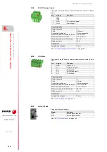
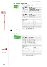
Plug-in part. 10-pole Phoenix-contact minicombicon connector (3.5
mm pitch).
Pin
Signal
Function
1
+5 V
Power supply.
2
- - -
- - -
3
- - -
- - -
4
MPG3-B
B signal of the third handwheel.
5
MPG3-A
A signal of the third handwheel.
6
MPG2-B
B signal of the second handwheel.
7
MPG2-A
A signal of the second handwheel.
8
MPG1-B
B signal of the first handwheel.
9
MPG1-A
A signal of the first handwheel.
10
GND
Power supply.
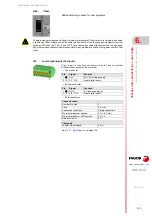
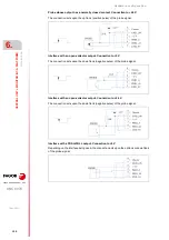
Always connect the shield of the cable to the ground plate using a metallic clamp. See
Содержание CNC 8070
Страница 1: ...Ref 1911 8070 CNC Hardware configuration...
Страница 8: ...BLANK PAGE 8...
Страница 14: ...BLANK PAGE 14...
Страница 18: ...BLANK PAGE 18...
Страница 22: ...BLANK PAGE 22...
Страница 24: ...BLANK PAGE 24...
Страница 26: ...BLANK PAGE 26...
Страница 28: ...Hardware configuration CNC 8070 1 PREVIOUS INFORMATION 28 REF 1911...
Страница 38: ...Hardware configuration CNC 8070 2 CONFIGURATION General diagram for U60 Q7 A platform 38 REF 1911...
Страница 94: ...Hardware configuration CNC 8070 6 CENTRAL UNIT MONITOR Q7 A PLATFORM 94 REF 1911 C70 15AT...
Страница 184: ...Hardware configuration CNC 8070 8 LCD 15SVGA PASSIVE MONITOR LCD15 SVGA Overall connection 184 REF 1911...
Страница 272: ...Hardware configuration CNC 8070 18 INSTALLING A SENSOR FOR GAP CONTROL LASER MODEL 272 REF 1911...
Страница 273: ...Hardware configuration CNC 8070 273 User notes REF 1911...
Страница 274: ...Hardware configuration CNC 8070 274 User notes REF 1911...
Страница 275: ...Hardware configuration CNC 8070 275 User notes REF 1911...


