Hardware configuration.
CNC 8070
6.
CEN
T
RAL UNIT + MONITOR (Q7-A
PLATFORM).
Conn
ecti
ons.
·128·
(R
EF
: 1911)
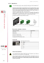
6.8.10 EtherCAT bus.
EtherCAT is an Ethernet-based communication protocol for connecting the CNC to remote
I/Os profile modules (proprietary or third-party). EtherCAT is configured as an inline topology,
where the CNC is the master and the other resources are distributed by nodes (up to 32).
The bus master interprets the ENI (EtherCAT Network Information) files generated by a
configurator and initializes the slaves connected to the bus.
This bus is compatible with the CAN bus, responsible for the management of keyboards and
operator panels. The CNC may have remote I/Os on both buses simultaneously
(CAN/EtherCAT), provided that both buses are not using the same resources.
Resources available on the bus.
Connector.
Cable characteristics.
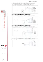
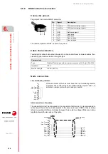
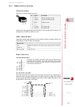
Fagor Automation supplies the required cables for EtherCAT communication; when using
third-party cables, these must be of the same category as those supplied by Fagor (see
tables). There are different types of cables depending on length and dynamic and static
installation characteristics.
To connect third-party modules on the bus, first acquire the software option “SOFT THIRD PARTY IOs”.
i
Bus EtherCAT with CNC (master) and RIOW-E Inline nodes.
Resources of the bus.
Total in the bus.
Digital inputs.
1024
Digital outputs.
1024
General purpose analog inputs.
40
General purpose analog outputs.
40
Analog inputs for Pt100 temperature sensors.
10
Master
Node 1
Node 2
EtherCAT bus
B64
X1(IN)
X2(OUT)
X1(IN)
X2(OUT)
Node n
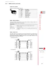
RJ45 connectors for 4-wire cable.
Pin.
Signal.
1
TD +
2
TD -
3
RD +
4
- - -
5
- - -
6
RD -
7
- - -
8
- - -
Use a specific EtherCAT cable. EtherCAT cables should never be installed next to power cables and
they should never cross over each other at a 90 degree angle.
Содержание CNC 8070
Страница 1: ...Ref 1911 8070 CNC Hardware configuration...
Страница 8: ...BLANK PAGE 8...
Страница 14: ...BLANK PAGE 14...
Страница 18: ...BLANK PAGE 18...
Страница 22: ...BLANK PAGE 22...
Страница 24: ...BLANK PAGE 24...
Страница 26: ...BLANK PAGE 26...
Страница 28: ...Hardware configuration CNC 8070 1 PREVIOUS INFORMATION 28 REF 1911...
Страница 38: ...Hardware configuration CNC 8070 2 CONFIGURATION General diagram for U60 Q7 A platform 38 REF 1911...
Страница 94: ...Hardware configuration CNC 8070 6 CENTRAL UNIT MONITOR Q7 A PLATFORM 94 REF 1911 C70 15AT...
Страница 184: ...Hardware configuration CNC 8070 8 LCD 15SVGA PASSIVE MONITOR LCD15 SVGA Overall connection 184 REF 1911...
Страница 272: ...Hardware configuration CNC 8070 18 INSTALLING A SENSOR FOR GAP CONTROL LASER MODEL 272 REF 1911...
Страница 273: ...Hardware configuration CNC 8070 273 User notes REF 1911...
Страница 274: ...Hardware configuration CNC 8070 274 User notes REF 1911...
Страница 275: ...Hardware configuration CNC 8070 275 User notes REF 1911...


