Operating Instructions
J22 TDLAS Gas Analyzer
34
Hauser
7.
Adjust the bypass flow meter (4) to set point, then adjust the analyzer flow meter (5) using the process gas at the
maximum expected backpressure.
Adjust the flow if the gas composition or backpressure changes
.
8.
For systems with an enclosure, close the enclosure door.
4.9.1
Setting the flow switch
The flow switch is factory set to 0.3 LPM and should not require adjustment at installation. However, to check or re-
set the flow switch, use the following procedure and a multimeter in continuity mode, or
1.
Set the gas to a minimum 0.3 LPM. (1)
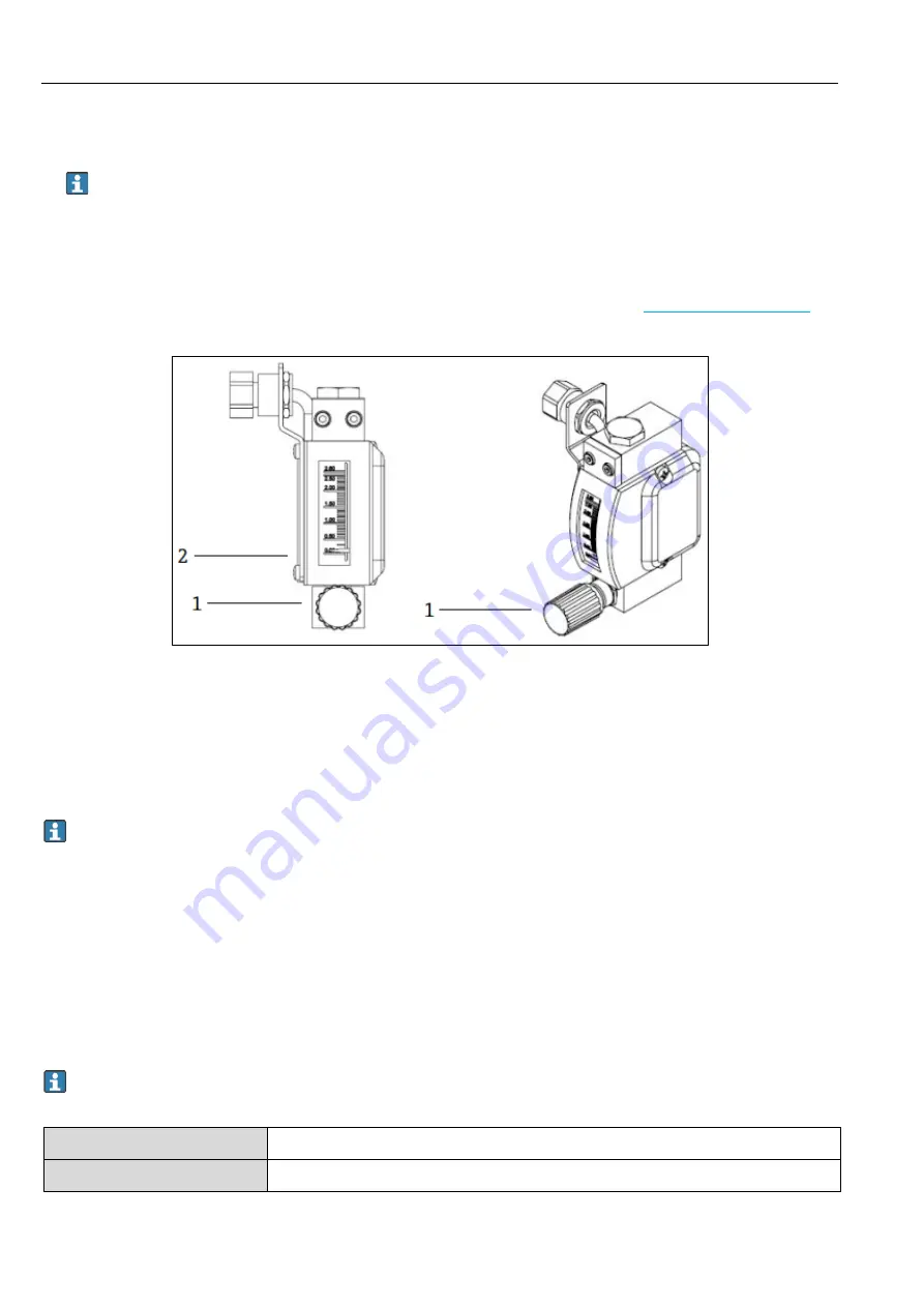
Fig 35. Flow switch adjustments
1
Adjustable nut
2
Needle valve adjustment
2.
Loosen the nut on the flow switch. (2)
3.
Adjust the reed cartridge (1) to the desired value, minimum 0.3 LPM, until the alarm is activated.
4.
Set the flow to the desired flow rate of 0.5 to 1 LPM. The alarm should resolve and change state.
5.
Secure the nut. (1)
In normal operation, the alarm has a 60 second delay
.
4.9.2
Setting the J22 TDLAS Gas Analyzer address
Depending on the fieldbus, the hardware addressing works differently; Modbus RS485 uses a device address, or
Modbus TCP, uses an IP address.
Hardware addressing for Modbus RS485
The device address must always be configured for a Modbus server. The valid device addresses are in the range from
1 to 247. If an address is not configured correctly, the measuring device is not recognized by the Modbus client. All
measuring devices are delivered from the factory with the device address 247 and with the software addressing
address mode.
Each address may only be assigned once in a Modbus RS485 network.
If all DIP switches are ON or OFF, all hardware addressing is OFF.
Modbus device address range
1 to 247
Addressing mode
Software addressing; all DIP switches for hardware addressing are set to OFF.
Содержание SpectraSensors J22 TDLAS
Страница 2: ...Operating Instructions J22 TDLAS Gas Analyzer 2 Endress Hauser...
Страница 150: ...www addresses endress com...


