B - 50
Appendix B
•
Vission 20/20 Application Procedures
Vission 20/20 • Operation and Service Manual • Emerson • 35391SC 2.7
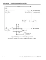
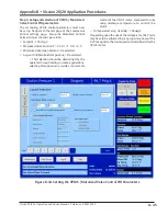
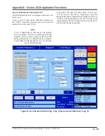
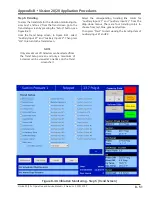
Figure B-39. Vibration Monitoring - Step 5 (Auxiliary I/O Screen, Page 3)
Step 5: Set Up Alarms and Trips
From the Auxiliary I/O screen, page 3, setup the alarms
and trips for Aux 1 and Aux 2.
In the example shown in Figure B-39, for Aux 1,
the “Alarm Only” is selected. The “Low Alarm”
setpoint is set to “-1.0 in,sec” so that the low
alarm will not activate. The “High Alarm” is set to
“1.0 in,sec” so when that setpoint is reached, the alarm
will activate. The “Low Trip” and “High Trip” setpoints
are left at “0.0 in,sec” since the “Alarm Only” is selected.
The “Delay” is set to “5 sec”.
NOTE
The “Delay” setpoint is the amount of time
monitored when the setpoint is reached. For
example, if the setpoint continues to be equal or
greater past the “Delay” time, then the alarm or trip
will activate.
In the example shown in Figure B-39, for “Aux 2: Fault
Detector”, the alarm and trip are both selected with
the selection of “Both” from the drop-down menu. The
“Low Alarm” setpoint is set to “-10.0 PV g” so that the
low alarm will not activate. The “High Alarm” is set to
“20.0 PV g” so when that setpoint is reached, the alarm
will activate. The “Low Trip” is set to “-10.0 PV g” so that
the low trip will not activate. The “High Trip” is set to
“40.0 PV g” so when that setpoint is reached, the trip will
activate. The “Delay” is set to “60 sec”.
Содержание Vilter Vission 20/20
Страница 1: ...Vission 20 20TM Micro controller Operation and service manual Version 2 7 ...
Страница 2: ......
Страница 4: ......
Страница 220: ...B 2 Blank Vission 20 20 Operation and Service Manual Emerson 35391SC 2 7 ...
Страница 300: ...D 2 Blank Vission 20 20 Operation and Service Manual Emerson 35391SC 2 6 ...
Страница 336: ......
Страница 337: ......

