TOC - 8
Vission 20/20 • Operation and Service Manual • Emerson • 35391SC 2.7
List of Tables and Figures
Table/Figure
Page Number
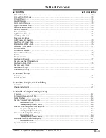
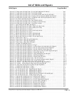
Table 3-1. Digital I/O ..............................................................................................................................3-3
Table 3-2. Analog Inputs.........................................................................................................................3-5
Table 3-3. Analog Outputs......................................................................................................................3-7
Table 3-4. Analog Input Jumper Tables ...................................................................................................3-12
Table 6-1. Compressor Size and Liquid Injection Outlet Port Direction ....................................................6-19
Table 6-2. Step VI Digital Outputs depending on Volume Ratio ...............................................................6-22
Table 10-1. Status Symbols ....................................................................................................................10-3
Table 14-1. Command Shaft Rotation Required By Actuator ...................................................................14-6
Table 14-2. Slide Valve Troubleshooting Guide .......................................................................................14-7
Table 14-3. LED Blink Codes and Troubleshooting Guide .........................................................................14-10
Table 22-1. Security Access Levels ..........................................................................................................22-3
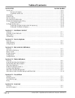
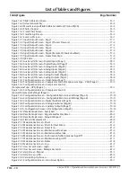
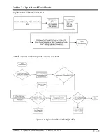
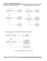
Figure 1-1. Operational Flow Charts .......................................................................................................1-1
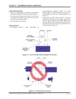
Figure 2-1. Vission 20/20 with Individual Transformer ............................................................................2-1
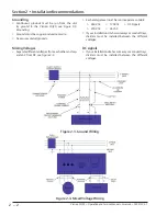
Figure 2-2. EMI and Vission 20/20 ..........................................................................................................2-1
Figure 2-3. Ground Wiring .....................................................................................................................2-2
Figure 2-4. Mixed Voltage Wiring ...........................................................................................................2-2
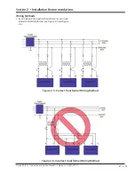
Figure 2-5. Correct Transformer Wiring Method ....................................................................................2-3
Figure 2-6. Incorrect Transformer Wiring Method ..................................................................................2-3
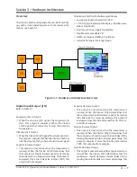
Figure 3-1. Hardware Architecture Overview .........................................................................................3-1
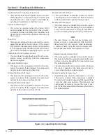
Figure 3-2. Liquid Injection #1 logic ........................................................................................................3-2
Figure 3-3. Liquid Injection #2 logic ........................................................................................................3-4
Figure 3-4. Digital I/O Board Layout........................................................................................................3-8
Figure 3-5. Digital Output Board Layout .................................................................................................3-9
Figure 3-6. Digital Input Board Layout ....................................................................................................3-10
Figure 3-7. Digital Input-Output Board Layout ........................................................................................3-11
Figure 3-8. Analog Input Board Layout ...................................................................................................3-12
Figure 3-9. Analog Output Board Layout ................................................................................................3-15
Figure 4-1. Main Screen..........................................................................................................................4-1
Figure 4-2. Top Status Bar ......................................................................................................................4-2
Figure 4-3. Parameter Bar ......................................................................................................................4-3
Figure 4-4. Unit Start Pop-Up Window ...................................................................................................4-4
Figure 4-5. Bottom Status Bar ................................................................................................................4-5
Figure 4-6. Splash Screen .......................................................................................................................4-6
Figure 4-7. Step VI Screen ......................................................................................................................4-7
Figure 4-8. SOI Solenoid Screen ..............................................................................................................4-8
Figure 4-9. Configurable Main Screen with Oil Pump and Oil Heater .......................................................4-9
Figure 4-10. Configurable Main Screen with SOI Solenoid and Oil Heater ................................................4-10
Figure 4-11. Configurable Main Screen with SOI Solenoid and Separator Level .......................................4-10
Figure 4-12. Configurable Main Screen with Step VI ...............................................................................4-11
Figure 4-13. Configurable Main Screen Default View ..............................................................................4-11
Figure 5-1. Menu Screen ........................................................................................................................5-1
Figure 5-2. Menu Screen with Remote Oil Cooler Enabled.......................................................................5-2
Figure 6-1. Compressor Control Screen - Suction Pressure Control .........................................................6-1
Figure 6-2. Compressor Control Screen - Process Temperature Control ..................................................6-2
Figure 6-3. Compressor Control Screen - Process Pressure Control .........................................................6-3
Figure 6-4. Proportional Band & Setpoint ...............................................................................................6-4
Figure 6-5. Compressor Control Screen - Discharge Pressure Control .....................................................6-4
Figure 6-6. Compressor Control Screen - VFD Settings Control ...............................................................6-5
Figure 6-7. VFD One-Step Control Method .............................................................................................6-6
Figure 6-8. VFD Two-Step Control Method .............................................................................................6-6
Figure 6-9. Compressor Control Screen - Oil Restriction Solenoid ...........................................................6-7
Figure 6-10. Compressor Control Screen - Rapid Cycling VFD Control ....................................................6-8
Figure 6-11. Compressor Control Screen - Pumpdown/Pulldown Control ...............................................6-10
Содержание Vilter Vission 20/20
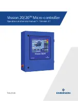
Страница 1: ...Vission 20 20TM Micro controller Operation and service manual Version 2 7 ...
Страница 2: ......
Страница 4: ......
Страница 220: ...B 2 Blank Vission 20 20 Operation and Service Manual Emerson 35391SC 2 7 ...
Страница 300: ...D 2 Blank Vission 20 20 Operation and Service Manual Emerson 35391SC 2 6 ...
Страница 336: ......
Страница 337: ......

