2
2
2-66
2-66
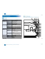
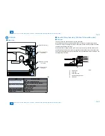
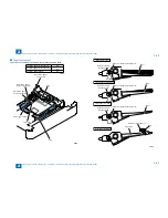
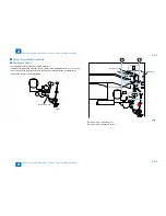
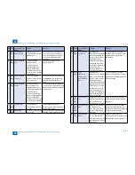
Technology > Pickup Feed System > Controls > Cassette Pickup Assembly (250-sheet 1st cassette model)
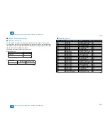
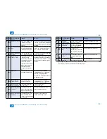
Technology > Pickup Feed System > Controls > Cassette Pickup Assembly (250-sheet 1st cassette model)
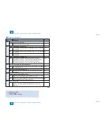
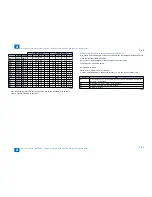
Width detection
Length detection
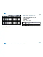
Width
Length
1
2
3
4
1
2
3
4
B5
257.0 182.0
0
ON
ON
0
0
0
0
0
EXEC
267.0
184.0
0
ON
ON
0
0
0
0
0
16K
270.0 195.0
0
ON
ON
0
ON
0
0
0
A5-R
148.5 210.0
ON
0
ON
0
ON
ON
0
0
A4
297.0 210.0
0
ON
0
0
ON
ON
0
0
STMT-R 139.7 215.9
ON
0
ON
0
ON
ON
0
0
LTR
279.4 215.9
0
ON
ON
0
ON
ON
0
0
B5-R
182.0 257.0
ON
0
ON
0
0
ON
ON
ON
LTR-R
215.9 279.4
0
0
ON
0
ON
0
0
ON
A4-R
210.0 297.0
0
0
ON
0
0
ON
ON
0
LGL
215.9 355.6
0
0
ON
0
ON
ON
0
ON
B4
257.0 364.0
0
ON
ON
0
ON
ON
ON
0
8K
270.0 390.0
0
ON
ON
0
ON
ON
ON
ON
A3
297.0 420.0
0
ON
0
0
0
0
ON
ON
LDR
279.4 431.8
0
ON
ON
0
0
0
ON
ON
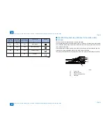
Also, the cassette presence is detected when the size switch is pushed. (If no switch is
pushed, it is determined as no cassette.)
T-2-36
T-2-36
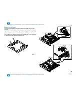
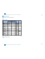
Setting method when the size detection patterns are overlapped
Size should be found manually on the check screen for the combination of A5-Rand STMT-R
or the combination of B5-R and EXEC.
Specify the ecognition method for the special paper with user setting.
The setting size is indicated below.
Related Service Mode
PRINT> CST> CASX> CSTX-UY> Number
X shows Cassette Number. Y shows size category. (X, Y is one of the number 1/2/3/4.)
U-size.
Size
U1
26: OFI, 27: E-OFI, 37: M-OFI, 36: A-OFI, 24: FLSP, 25: A-FLSP, 30: A-LTRR, 42:
FA4, 34: G-LGL 0: default
U2
32: G-LTR-R, 34: G-LGL, 23: K-LGL-R, 0: default
U3
22: K-LGL, 31: G-LTR, 29: A-LTR, 0: default
U4
28: B-OFI, 0: default
T-2-37
T-2-37
Содержание IMAGERUNNER 2530
Страница 1: ...9 8 7 6 5 4 3 2 1 imageRUNNER 2530 2525 2520 Series Service Manual...
Страница 4: ...Blank Page...
Страница 16: ...1 1 Product Overview Product Overview Product Lineup Feature Specifications Name of Parts...
Страница 111: ...3 3 Periodical Service Periodical Service Consumable Parts and Cleaning Parts...
Страница 159: ...5 5 Adjustment Adjustment Outline Adjustment when replacing parts Image position adjustment...
Страница 166: ...6 6 Troubleshooting Troubleshooting Upgrading Targets and Procedure...
Страница 171: ...7 7 Error Code Error Code Overview Error Code Jam Code Alarm Code...
Страница 186: ...8 8 Service Mode Service Mode Outline Details of Service Mode...
Страница 321: ...Service Tools General Circuit Diagram Appendix...

