9
9
9-37
9-37
Installation > Control Interface Cable-A1 Installation Procedure > Installation Procedure
Installation > Control Interface Cable-A1 Installation Procedure > Installation Procedure
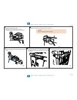
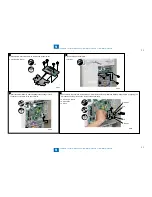
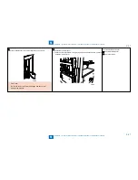
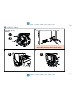
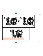
9) Cut the blindfold cover from the rear-left cover using nippers.
CAUTION:
Be sure to remove the remaining edges with care not to
damage the harness.
F-9-82
F-9-82
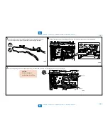
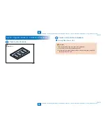
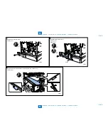
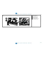
10) Install the controller cover.
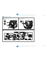
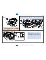
11) Pass the control card cable in the opening made as mentioned above, and then
install the rear-left cover.
F-9-83
F-9-83
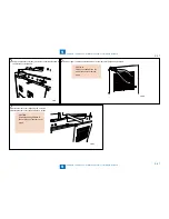
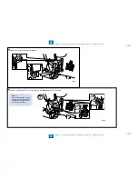
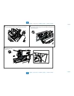
12) Install the removed cover.
Rear-left blindfold cover
Rear cover (right)
Содержание IMAGERUNNER 2530
Страница 1: ...9 8 7 6 5 4 3 2 1 imageRUNNER 2530 2525 2520 Series Service Manual...
Страница 4: ...Blank Page...
Страница 16: ...1 1 Product Overview Product Overview Product Lineup Feature Specifications Name of Parts...
Страница 111: ...3 3 Periodical Service Periodical Service Consumable Parts and Cleaning Parts...
Страница 159: ...5 5 Adjustment Adjustment Outline Adjustment when replacing parts Image position adjustment...
Страница 166: ...6 6 Troubleshooting Troubleshooting Upgrading Targets and Procedure...
Страница 171: ...7 7 Error Code Error Code Overview Error Code Jam Code Alarm Code...
Страница 186: ...8 8 Service Mode Service Mode Outline Details of Service Mode...
Страница 321: ...Service Tools General Circuit Diagram Appendix...


