8
8
8-8
8-8
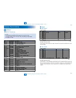
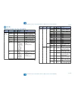
Service Mode > Details of Service Mode > #SSSW > Details
Service Mode > Details of Service Mode > #SSSW > Details
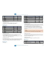
Bit
Function
1
0
2
Convert "inch" into "mm" when transmitting the
received image data
convert
do not convert
3
not used
-
-
4
not used
-
-
5
not used
-
-
6
not used
-
-
7
not used
-
-
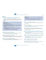
Detailed Discussions of Bit 2
It converts "inch" into "mm" when transmitting the received image data.
Scanning direction in conversion follows the Bit 2 setting of SW14.
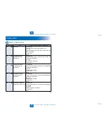
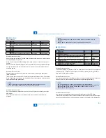
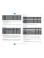
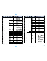
SSSW-SW014
List of Functions
Bit
Function
1
0
0
not used
-
-
1
not used
-
-
2
direction of scanning for inch/mm conversion
both main and sub
scanning directions
sub scanning
direction only
3
not used
-
-
4
inch-configuration resolution declaration
declare
do not declare
5
not used
-
-
6
not used
-
-
7
not used
-
-
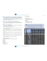
Detailed Discussions of Bit 2
Use it to specify whether to convert or not convert an inch-configuration resolution into a
millimeter-configuration resolution for image read in G3 transmission:
either in sub scanning direction only or in both main and sub scanning directions. The setting
is valid only when bit 1 of SW05 of #SSSW is set to '1'.
Detailed Discussions of Bit 4
Use it to specify whether to declare or not declare an inch-configuration resolution to the other
machine for G3 communication: if 'declare' is selected, the machine will indicate that it reads
and records at an inch-configuration resolution using the DIS, DCS, or DTC signal.
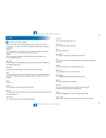
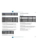
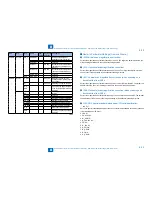
SSSW-SW15
List of Functions
●
●
T-8-13
T-8-13
T-8-14
T-8-14
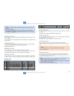
Bit
Function
1
0
0
not used
-
-
1
timing for storing polarity in memory
telephone line
after CI detection
2
Reception of call through caller ID display line
(main unit line)
Yes
No
3
not used
-
-
4
not used
-
-
5
not used
-
-
6
Detection of continuous signal at fax/tel
switchover
Yes
No
7
not used
-
-
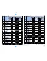
Detailed Discussions of Bit 1
When a dial-in fax/tel switch-cover takes place, the polarity of the telephone line is stored in
memory for detection of reversal of the polarity of the telephone line. The timing may be set
so that it is either after detection of CI or after release of the telephone line.
Some switchboards are known to wrongly store the polarity, which can further cause
the machine to enter standby state when the telephone line is released, thus disabling
communication with the other party. If such is the case, be sure to select ‘after release of
telephone line’.
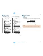
CAUTION:
If the switch is set to ‘after release of telephone line’, the reversal of the polarity cannot
be detected from when CI is detected to when the telephoneline is released.
Detailed Discussions of Bit 2
When a machine which is not compatible with the caller ID display/modem dial-in service is
connected to the subscriber line which is compatible with that service, the "main unit line" is
made ready for receiving the incoming call.
Detailed Discussions of Bit 6
Select whether to detect a continuous ROT signal at FAX/TEL switchover.
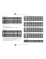
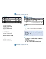
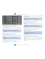
SSSW-SW16
List of Functions
Bit
Function
1
0
0
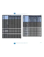
No Paper display conditions
Same size fax paper Either one All fax
paper
1
Check side cassette paper at No Paper display Do not check
Check
●
T-8-15
T-8-15
Содержание IMAGERUNNER 2530
Страница 1: ...9 8 7 6 5 4 3 2 1 imageRUNNER 2530 2525 2520 Series Service Manual...
Страница 4: ...Blank Page...
Страница 16: ...1 1 Product Overview Product Overview Product Lineup Feature Specifications Name of Parts...
Страница 111: ...3 3 Periodical Service Periodical Service Consumable Parts and Cleaning Parts...
Страница 159: ...5 5 Adjustment Adjustment Outline Adjustment when replacing parts Image position adjustment...
Страница 166: ...6 6 Troubleshooting Troubleshooting Upgrading Targets and Procedure...
Страница 171: ...7 7 Error Code Error Code Overview Error Code Jam Code Alarm Code...
Страница 186: ...8 8 Service Mode Service Mode Outline Details of Service Mode...
Страница 321: ...Service Tools General Circuit Diagram Appendix...

