9
9
9-82
9-82
Installation > Drum Heater-C1 Installation Procedure > Installation Procedure
Installation > Drum Heater-C1 Installation Procedure > Installation Procedure
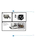
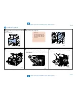
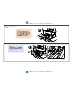
28) Restore the power supply unit with 3 screws and joint all the connectors for it.
29) Restore the toner replenish cover, the rear cover (right), the connector cover, the rear lower cover, the left lower cover, the left cover, the blindfold cover and the left rear cover.
30) Restore the inner bottom cover and fix 1 screw to the left cover.
x1
x3
F-9-194
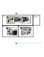
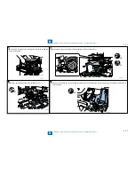
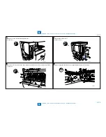
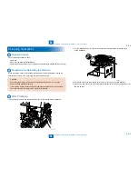
31) Restore the developing unit and joint the developing unit connector.
32) Hold the drum unit handle and the part shown in the figure. Slowly draw it in till it stops.
CAUTION:
Confirm engagement of the drum unit and the drum unit rail of the host machine.
F-9-195
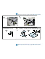
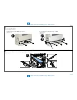
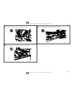
33) Turn the developing pressure lever to set the developing unit and fix 1 screw.
The screw is not necessary if it is not removed at the step 5).
x1
F-9-196
Содержание IMAGERUNNER 2530
Страница 1: ...9 8 7 6 5 4 3 2 1 imageRUNNER 2530 2525 2520 Series Service Manual...
Страница 4: ...Blank Page...
Страница 16: ...1 1 Product Overview Product Overview Product Lineup Feature Specifications Name of Parts...
Страница 111: ...3 3 Periodical Service Periodical Service Consumable Parts and Cleaning Parts...
Страница 159: ...5 5 Adjustment Adjustment Outline Adjustment when replacing parts Image position adjustment...
Страница 166: ...6 6 Troubleshooting Troubleshooting Upgrading Targets and Procedure...
Страница 171: ...7 7 Error Code Error Code Overview Error Code Jam Code Alarm Code...
Страница 186: ...8 8 Service Mode Service Mode Outline Details of Service Mode...
Страница 321: ...Service Tools General Circuit Diagram Appendix...

