


2
2
2-25
2-25
Technology > Controller System > Controls > Power supply
Technology > Controller System > Controls > Power supply
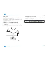
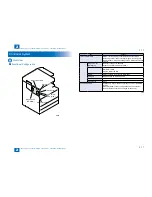
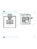
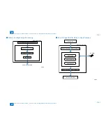
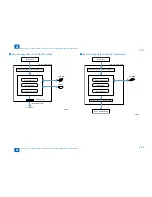
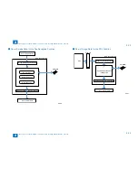
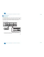
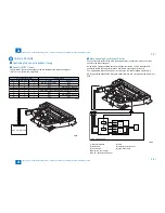
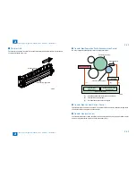
Power supply
Internal power supply
Main SW
Power
supply PCB
Option
power supply
PCB
Heater
PCB
Low-voltage
power supply
circuit
+5Vcircuit
+24Vcircuit
Drum heater
Reader heater
Cassette heater
Fixing heater
+24V
+5V
R
+24VR
+5VC
USB HUB Kit
Interlock
switch (SW2)
+24VR
+24VU
+24VR
+24VR
Reader
relay PCB
ADF
CIS
Main controller PCB
DC controller PCB
+24VR
+5VR
+24VR
+5VC
+24VU
+24VR
+24VS
+5VR
+3.3V
+5VC
+3.3V
+5VR
Regulator
+3.3V
+3.3
V
+5VC
Modem PCB
VH PCB
HVT PCB
Laser scanner
unit
+5VC
+12VR
No.2 deleivery
unit
+5VR
+3.3V
+3.3V
+24VR
+24VR
+24VR
Cassette
pedestal
Inner finisher
+5VR
+24VU
+24VR
Option
+3.3
V
+24VR
+3.3V
+24VR
Regulator
+12VR
■
●
F-2-44
F-2-44
Содержание IMAGERUNNER 2530
Страница 1: ...9 8 7 6 5 4 3 2 1 imageRUNNER 2530 2525 2520 Series Service Manual...
Страница 4: ...Blank Page...
Страница 16: ...1 1 Product Overview Product Overview Product Lineup Feature Specifications Name of Parts...
Страница 111: ...3 3 Periodical Service Periodical Service Consumable Parts and Cleaning Parts...
Страница 159: ...5 5 Adjustment Adjustment Outline Adjustment when replacing parts Image position adjustment...
Страница 166: ...6 6 Troubleshooting Troubleshooting Upgrading Targets and Procedure...
Страница 171: ...7 7 Error Code Error Code Overview Error Code Jam Code Alarm Code...
Страница 186: ...8 8 Service Mode Service Mode Outline Details of Service Mode...
Страница 321: ...Service Tools General Circuit Diagram Appendix...


