9
9
9-74
9-74
Installation > Drum Heater-C1 Installation Procedure > Installation Procedure
Installation > Drum Heater-C1 Installation Procedure > Installation Procedure
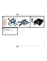
Installation Procedure
1) Turn the main power OFF and unplug the power cord from
the outlet.
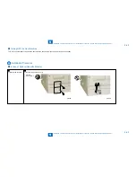
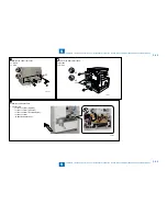
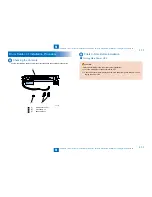
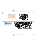
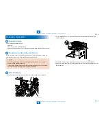
2) Open the front cover.
F-9-166
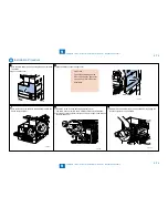
3) Push the button to open the right cover.
CAUTION:
To avoid any damage on the
drum unit, keep the right cover
open by 5 cm or more during
installation.
F-9-167
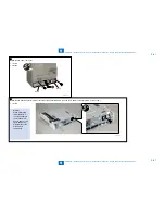
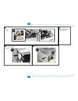
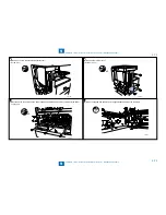
4) Turn the lock lever as shown in the figureand remove the
waste toner container.
F-9-168
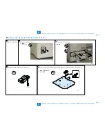
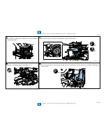
5) Remove 1 screw from the developing pressure lever.
The screw does not exist in some machine versions by destination.
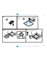
6) Turn the developing pressure lever as shown in the figure and release
the developing unit.
x1
F-9-169
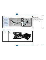
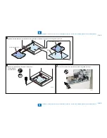
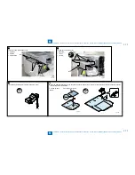
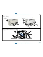
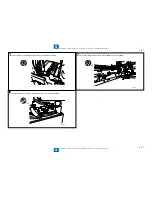
7) Slowly draw out the drum unit by half as shown while gripping the
lever beneath the drum unit handle.
F-9-170
Содержание IMAGERUNNER 2530
Страница 1: ...9 8 7 6 5 4 3 2 1 imageRUNNER 2530 2525 2520 Series Service Manual...
Страница 4: ...Blank Page...
Страница 16: ...1 1 Product Overview Product Overview Product Lineup Feature Specifications Name of Parts...
Страница 111: ...3 3 Periodical Service Periodical Service Consumable Parts and Cleaning Parts...
Страница 159: ...5 5 Adjustment Adjustment Outline Adjustment when replacing parts Image position adjustment...
Страница 166: ...6 6 Troubleshooting Troubleshooting Upgrading Targets and Procedure...
Страница 171: ...7 7 Error Code Error Code Overview Error Code Jam Code Alarm Code...
Страница 186: ...8 8 Service Mode Service Mode Outline Details of Service Mode...
Страница 321: ...Service Tools General Circuit Diagram Appendix...

