0
0
0-8
0-8
Removing the Developing Assembly -----------------------------------------4-36
Removing the Manual Feed Pickup Roller ---------------------------------4-36
Removing the Manual Feed Separation Pad ------------------------------4-37
Removing the Fixing Unit -------------------------------------------------------4-38
Removing the Cassette Pickup Roller (250-sheet 1st Cassette Model) 4-38
Removing the Roller Cassette Separation Pad (250-sheet 1st Cassette Model) 4-39
Removing the Cassette Pickup Roller (550-sheet 1st Cassette Model) 4-39
Removing the Cassette Transfer Roller (550-sheet 1st Cassette Model) 4-39
Removing the Cassette Separation Roller (550-sheet 1st Cassette Model) --4-40
Removing the Idler Gear (Only for 550-sheet 1st Cassette Model for China) 4-40
PCB ----------------------------------------------------------------------------- 4-41
Removing the DC Controller PCB --------------------------------------------4-41
Before Replacement/RAM Clearing---------------------------------------------------4-41
Replacement Procedure -----------------------------------------------------------------4-41
Action to Take after Replacement/RAM Clearing ----------------------------------4-41
Removing the Main Controller PCB ------------------------------------------4-41
Replacement Procedure -----------------------------------------------------------------4-41
Action to Take after Replacement -----------------------------------------------------4-41
Removing the RAM PCB --------------------------------------------------------4-42
Replacement Procedure -----------------------------------------------------------------4-42
5
Adjustmen
t
Outline ---------------------------------------------------------------------------5-2
Adjustment when replacing parts
---------------------------------------------- 5-2
Image position adjustment
------------------------------------------------------- 5-2
Adjustment when replacing parts
-----------------------------------------5-3
Scanning System ------------------------------------------------------------------ 5-3
Action to Take after Replacing the CIS Unit ------------------------------------------ 5-3
Action to Take after Replacing the Platen Glass ------------------------------------ 5-3
Action to Take after Replacing the ADF Scan Glass ------------------------------- 5-4
Controller System ------------------------------------------------------------------ 5-4
Action to Take after Replacing theMain Controller PCB -------------------------- 5-4
Action to Take when Replacing the DC Controller PCB
-------------------------- 5-4
Action to Take after Replacing the RAM ---------------------------------------------- 5-5
Laser Exposure System
---------------------------------------------------------- 5-5
Action to Take after Replacing the Laser Scanner Unit
--------------------------- 5-5
Image position adjustment
--------------------------------------------------5-6
Margin Along the Leading Edge
------------------------------------------------ 5-6
Left Image Margin
----------------------------------------------------------------- 5-6
Leading Edge Non-Image Width
----------------------------------------------- 5-6
Left Non-Image Width
------------------------------------------------------------ 5-7
6
Troubleshooting
Upgrading Targets and Procedure ----------------------------------------6-2
Outline -------------------------------------------------------------------------------- 6-2
Procedure ---------------------------------------------------------------------------- 6-3
7
Error Code
Overview
------------------------------------------------------------------------7-2
Outline -------------------------------------------------------------------------------- 7-2
Error Code ----------------------------------------------------------------------7-3
Error Code Details ----------------------------------------------------------------- 7-3
FAX Error Codes ------------------------------------------------------------------- 7-9
Outline ----------------------------------------------------------------------------------------- 7-9
User Error Code ----------------------------------------------------------------------------- 7-9
Service Error Code ------------------------------------------------------------------------- 7-9
Jam Code --------------------------------------------------------------------- 7-11
Main Unit ---------------------------------------------------------------------------- 7-11
DADF-AB1 --------------------------------------------------------------------------7-13
Inner Finisher-B1 ------------------------------------------------------------------7-14
Alarm Code ------------------------------------------------------------------- 7-15
Alarm Code Details ---------------------------------------------------------------7-15
8
Service Mode
Outline ---------------------------------------------------------------------------8-2
Outline of Service Mode ---------------------------------------------------------- 8-2
Using the Mode --------------------------------------------------------------------- 8-3
Setting of Bit Switch
--------------------------------------------------------------- 8-3
Outline ----------------------------------------------------------------------------------------- 8-3
Details of Service Mode -----------------------------------------------------8-4
#SSSW ------------------------------------------------------------------------------- 8-4
SSSW Composition ------------------------------------------------------------------------ 8-4
Details ----------------------------------------------------------------------------------------- 8-4
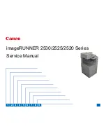
Содержание IMAGERUNNER 2530
Страница 1: ...9 8 7 6 5 4 3 2 1 imageRUNNER 2530 2525 2520 Series Service Manual...
Страница 4: ...Blank Page...
Страница 16: ...1 1 Product Overview Product Overview Product Lineup Feature Specifications Name of Parts...
Страница 111: ...3 3 Periodical Service Periodical Service Consumable Parts and Cleaning Parts...
Страница 159: ...5 5 Adjustment Adjustment Outline Adjustment when replacing parts Image position adjustment...
Страница 166: ...6 6 Troubleshooting Troubleshooting Upgrading Targets and Procedure...
Страница 171: ...7 7 Error Code Error Code Overview Error Code Jam Code Alarm Code...
Страница 186: ...8 8 Service Mode Service Mode Outline Details of Service Mode...
Страница 321: ...Service Tools General Circuit Diagram Appendix...

