9
9
9-36
9-36
Installation > Control Interface Cable-A1 Installation Procedure > Installation Procedure
Installation > Control Interface Cable-A1 Installation Procedure > Installation Procedure
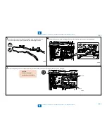
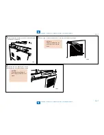
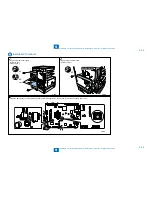
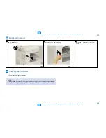
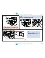
5) To remove the core, cut the cable holder at the position shown below using nippers.
6) Cut the cable ties, and then remove the core of the control card cable.
F-9-79
F-9-79
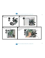
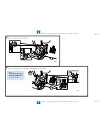
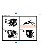
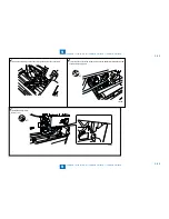
7) Connect the connector of the control card cable to the connector on the image processor PCB as
shown.
x1
F-9-80
F-9-80
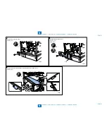
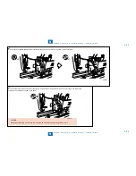
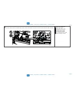
8) Route the harness as shown.
Clamp (1 pc.)
x1
•
F-9-81
F-9-81
Содержание IMAGERUNNER 2530
Страница 1: ...9 8 7 6 5 4 3 2 1 imageRUNNER 2530 2525 2520 Series Service Manual...
Страница 4: ...Blank Page...
Страница 16: ...1 1 Product Overview Product Overview Product Lineup Feature Specifications Name of Parts...
Страница 111: ...3 3 Periodical Service Periodical Service Consumable Parts and Cleaning Parts...
Страница 159: ...5 5 Adjustment Adjustment Outline Adjustment when replacing parts Image position adjustment...
Страница 166: ...6 6 Troubleshooting Troubleshooting Upgrading Targets and Procedure...
Страница 171: ...7 7 Error Code Error Code Overview Error Code Jam Code Alarm Code...
Страница 186: ...8 8 Service Mode Service Mode Outline Details of Service Mode...
Страница 321: ...Service Tools General Circuit Diagram Appendix...

