7
7
7-4
7-4
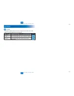
Error Code > Error Code > Error Code Details
Error Code > Error Code > Error Code Details
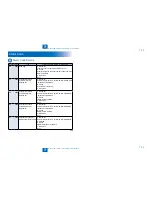
Ecode
Detail
Code
Item
Description
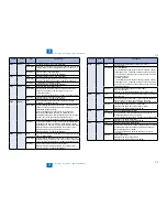
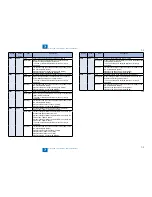
E014
0001
Title
Unstable rotation of the Fixing Motor (M2)
Description
Detection is executed every 100 msec after the start of motor
rotation; however, the drive detection signal is absent for 2
sec.
Remedy
1.Replace the Fixing Motor (M2).
2.Replace the DC Controller PCB (PCB4).
E014
0002
Title
Unstable rotation of the Fixing Motor (M2)
Description
During motor rotation, detection is executed every 100 msec;
however, the drive signal is absent 5 times in sequence.
Remedy
"1.Replace the Fixing Motor (M2).
2.Replace the DC Controller PCB (PCB4)."
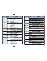
E019
0000
Title
Error in Waste Toner Sensor (S17)
Description
Warning when the sensor goes on for 2000 consecutive
sheets, and error when the sensor goes on for 100
consecutive sheets.
* Error occurs after the delivery if a paper in passage exists.
Remedy
1.Replace the Waste Toner Sensor (S17).
2.Replace the DC Controller PCB (PCB4).
E020
0000
Title
The path between the sub hopper and the developing
assembly is clogged with toner.
Description
The Developing Assembly Toner Sensor (TS1) detects the
absence of toner,while the Sub Hopper Toner Sensor (TS2)
detects the presence of toner.
With the Developing Cylinder Clutch (CL3) turned on,
the hopper feedscrew motor (M7) is rotated for 1 sec
intermittently 194 times; still, theDeveloping Assembly Toner
Sensor (TS1) does not detect the presence of toner.
* Error occurs after the delivery if a paper in passage exists.
Remedy
1.Check the rotation of hopper motor gear. (If rotating, false
detection by the sensor is doubted. Feed the toner to the
developing unit in service mode: CLEAR>ENGIN>TNRINST.)
2.Replace the Developing Assembly Toner Sensor (TS1).
3.Replace the Sub Hopper Toner Sensor (TS2).
4.Replace the DC Controller PCB (PCB4).
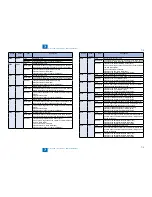
E024
0000
Title
The connector (J207) of Developing Assembly Toner Sensor
(TS1) is disconnected.
Description
The Developing Assembly Toner Sensor (TS1) connection
detection signal is absent for 100 msec 10 times in sequence.
* Error occurs after the delivery if a paper in passage exists.
Remedy
1.Check connection of the Connector (J207).
2.Replace the Developing Assembly Toner Sensor (TS1).
3.Replace the DC Controller PCB (PCB4).
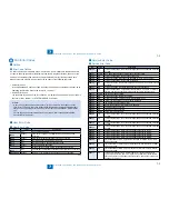
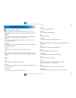
Ecode
Detail
Code
Item
Description
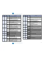
E024
0001
Title
The Developing Assembly Toner Sensor (TS1) is
disconnected.
Description
<At LOW SPEED>
- The developing assembly toner sensor (TS1) ON counter
is checked every 2.5 seconds, and the counter increments
1 count every 25 times when the sensor goes on, and 300
counts are reached.
<At HIGH SPEED>
- The developing assembly toner sensor (TS1) ON counter
is checked every 1.5 seconds, and the counter increments
1 count every 15 times when the sensor goes on, and 300
counts are reached.
Remedy
1.Check connection of the Connector (J207).
2.Correct the cable.
3.Replace the Developing Assembly Toner Sensor (TS1).
E025
0000
Title
The connector (J207) of Sub Hopper Toner Sensor (TS2) is
disconnected.
Description
The Sub Hopper Toner Sensor (TS2) connection detection
signal is absent for 100 msec 10 times in sequence.
* Error occurs after the delivery if a paper in passage exists.
Remedy
1.Check connection of the Connector (J207).
2.Replace the Sub Hopper Toner Sensor (TS2).
3.Replace the DC Controller PCB (PCB4).
E025
0001
Title
Failure of the Bottle Motor (M6)
Description
The bottle motor (M6) is unlocked when it goes on for 12
consecutive times at 0.1 sec. intervals.
* Error occurs after the delivery if a paper in passage exists.
Remedy
1.Replace the Bottle Motor (M6).
2.Replace the DC Controller PCB (PCB4).
E110
0001
Title
Failure of the Scanner Motor (M21)
Description
The Scanner Motor (M21) speed lock signal does not indicate
a locked state a specific period of time after the Scanner
Motor (M21) has been started.
* The same condition is detected after the error retry is
performed.
Remedy
1.Check the cable.
2.Replace the Laser Scanner Unit.
3.Replace the DC Controller PCB (PCB4).
Содержание IMAGERUNNER 2530
Страница 1: ...9 8 7 6 5 4 3 2 1 imageRUNNER 2530 2525 2520 Series Service Manual...
Страница 4: ...Blank Page...
Страница 16: ...1 1 Product Overview Product Overview Product Lineup Feature Specifications Name of Parts...
Страница 111: ...3 3 Periodical Service Periodical Service Consumable Parts and Cleaning Parts...
Страница 159: ...5 5 Adjustment Adjustment Outline Adjustment when replacing parts Image position adjustment...
Страница 166: ...6 6 Troubleshooting Troubleshooting Upgrading Targets and Procedure...
Страница 171: ...7 7 Error Code Error Code Overview Error Code Jam Code Alarm Code...
Страница 186: ...8 8 Service Mode Service Mode Outline Details of Service Mode...
Страница 321: ...Service Tools General Circuit Diagram Appendix...


