9
9
31
31
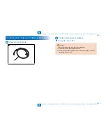
Installation > Serial Interface Kit-J2 Installation Procedure > Installation Procedure
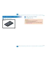
Installation > Serial Interface Kit-J2 Installation Procedure > Installation Procedure
Installation Procedure
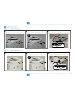
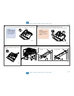
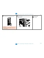
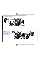
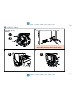
1) Remove the Power Supply Retainer and Power plug.
1 Screw
•
F-9-67
F-9-67
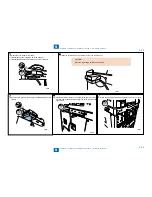
2) Remove the Rear cover (right).
3 Screws
2 Claws
•
•
Claws
x3
x2
F-9-68
F-9-68
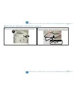
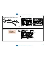
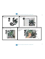
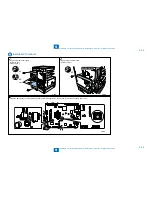
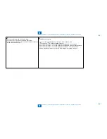
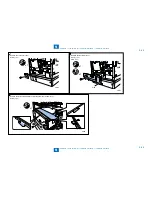
3) Remove the SD Card Cover and the Left Rear Cover, and cut off the part of the Left Rear Cover indicated in the figure below with nippers.
4 Screws
CAUTION:
When cutting
off with
nippers, be
sure to cut it
off fully.
•
x4
F-9-69
F-9-69
F-9-70
F-9-70
Содержание IMAGERUNNER 2530
Страница 1: ...9 8 7 6 5 4 3 2 1 imageRUNNER 2530 2525 2520 Series Service Manual...
Страница 4: ...Blank Page...
Страница 16: ...1 1 Product Overview Product Overview Product Lineup Feature Specifications Name of Parts...
Страница 111: ...3 3 Periodical Service Periodical Service Consumable Parts and Cleaning Parts...
Страница 159: ...5 5 Adjustment Adjustment Outline Adjustment when replacing parts Image position adjustment...
Страница 166: ...6 6 Troubleshooting Troubleshooting Upgrading Targets and Procedure...
Страница 171: ...7 7 Error Code Error Code Overview Error Code Jam Code Alarm Code...
Страница 186: ...8 8 Service Mode Service Mode Outline Details of Service Mode...
Страница 321: ...Service Tools General Circuit Diagram Appendix...


