9
9
9-63
9-63
Installation > Cassette Heater Unit 37 > Installation Procedure > In case of Options(CST. Feeding Unit)
Installation > Cassette Heater Unit 37 > Installation Procedure > In case of Options(CST. Feeding Unit)
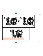
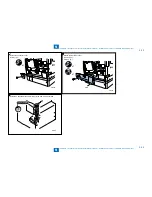
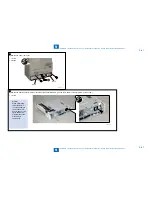
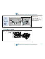
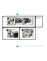
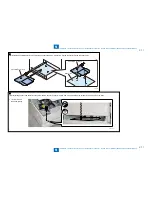
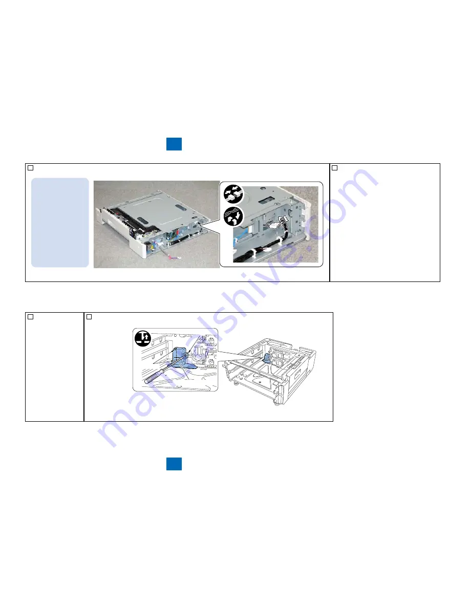
9) AT the rear side of the Cassette Module, pull out the connector at the heater side and the connect the connecter.
MEMO:
When performing
this procedure, it
is not necessary to
remove the main
body. However, the
figure shows the
picture without the
main body to
show easily.
F-9-137
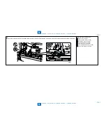
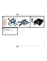
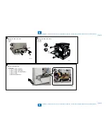
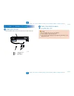
10) Install the Lower rear cover
11) Connect the 4 Connectors.
12) Install the Connector Cover.
13) Install the removed Cassettes.
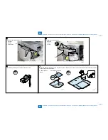
14) Check that the Environment Heater switch is ON
15) Plug the power plug of the host machine to the
outlet.
16) Turn ON the main power switch.
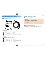
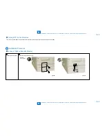
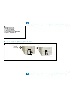
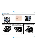
In case of Options(CST. Feeding Unit)
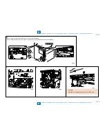
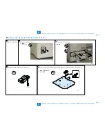
1) Remove the cassette.
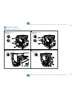
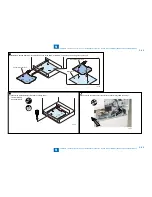
2) Remove the Heater Connector Cover using a flat-blade screwdriver.
1 Claw
2 Protrusions
•
•
Claw
Heater Connector Cover
Protrusions
F-9-138
■
Содержание IMAGERUNNER 2530
Страница 1: ...9 8 7 6 5 4 3 2 1 imageRUNNER 2530 2525 2520 Series Service Manual...
Страница 4: ...Blank Page...
Страница 16: ...1 1 Product Overview Product Overview Product Lineup Feature Specifications Name of Parts...
Страница 111: ...3 3 Periodical Service Periodical Service Consumable Parts and Cleaning Parts...
Страница 159: ...5 5 Adjustment Adjustment Outline Adjustment when replacing parts Image position adjustment...
Страница 166: ...6 6 Troubleshooting Troubleshooting Upgrading Targets and Procedure...
Страница 171: ...7 7 Error Code Error Code Overview Error Code Jam Code Alarm Code...
Страница 186: ...8 8 Service Mode Service Mode Outline Details of Service Mode...
Страница 321: ...Service Tools General Circuit Diagram Appendix...

